
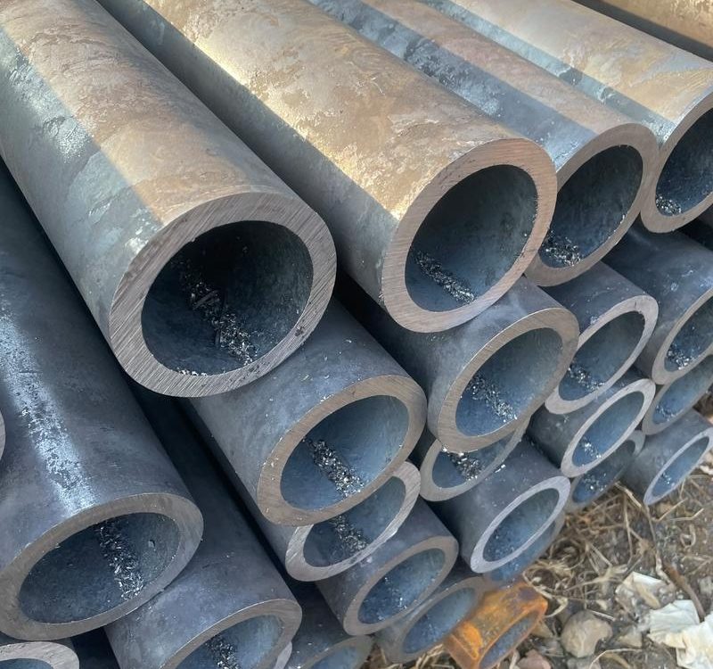
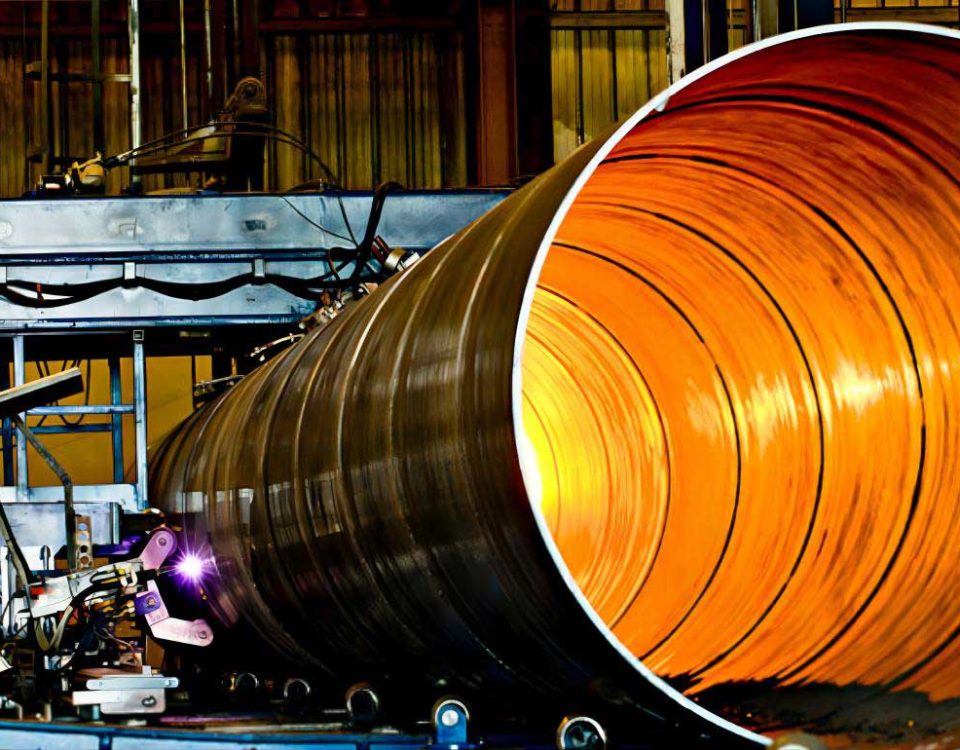
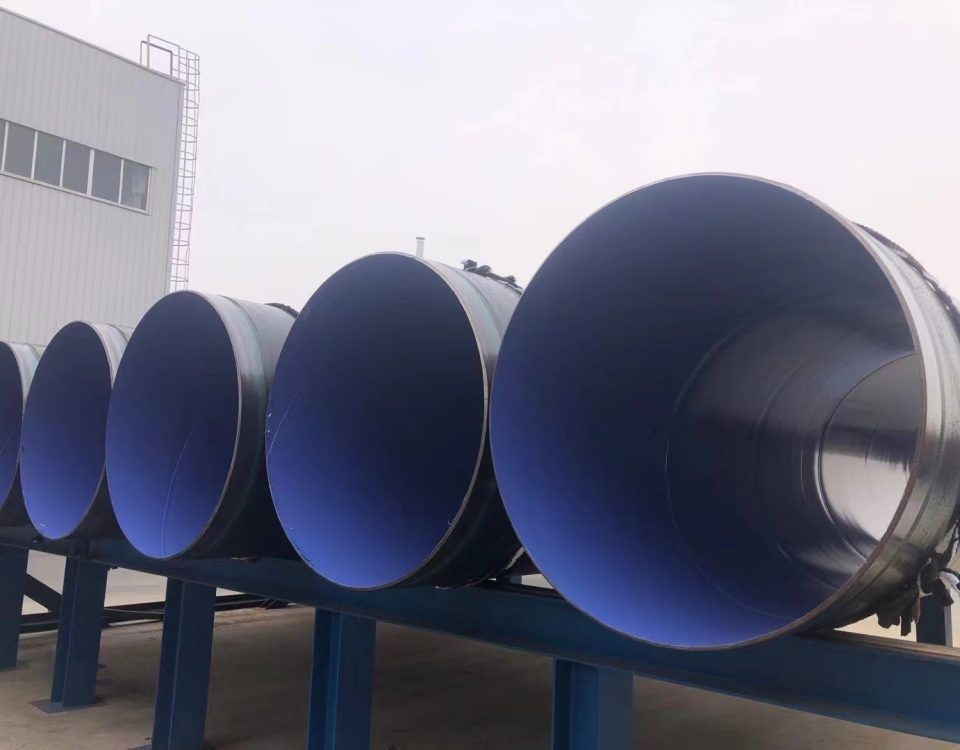
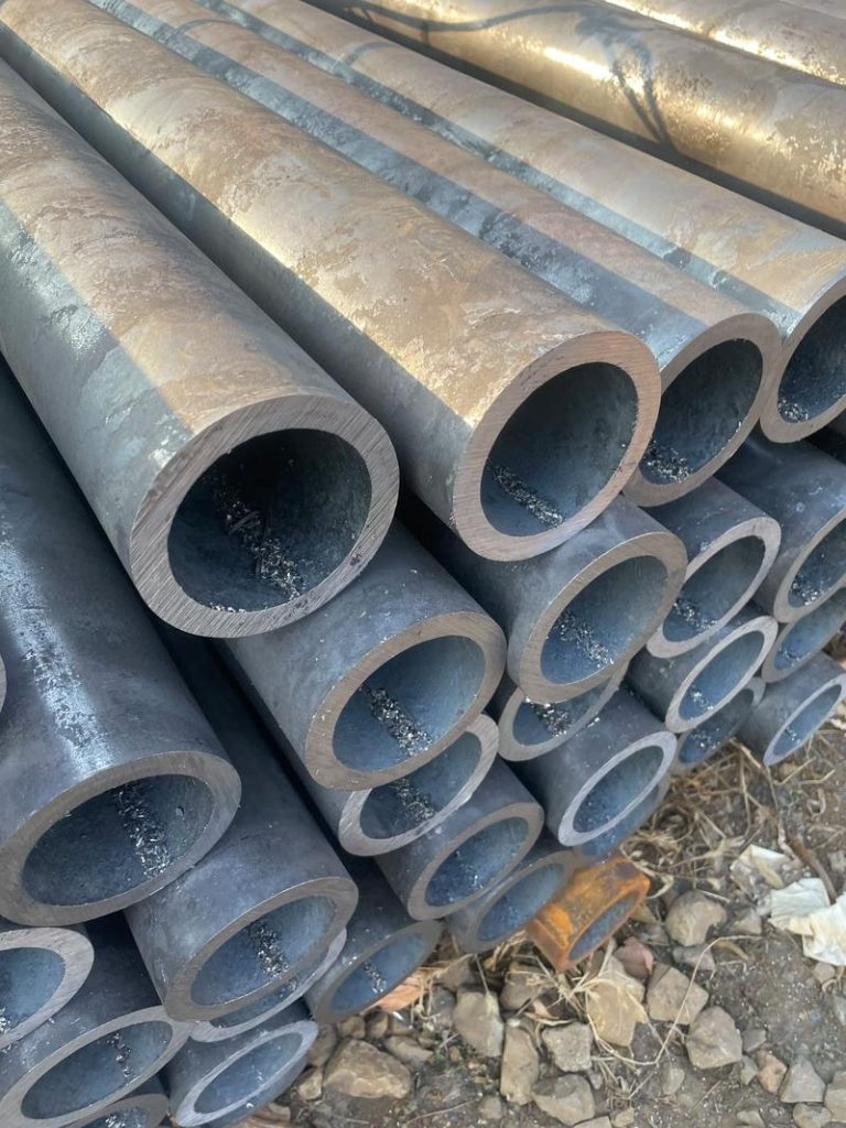
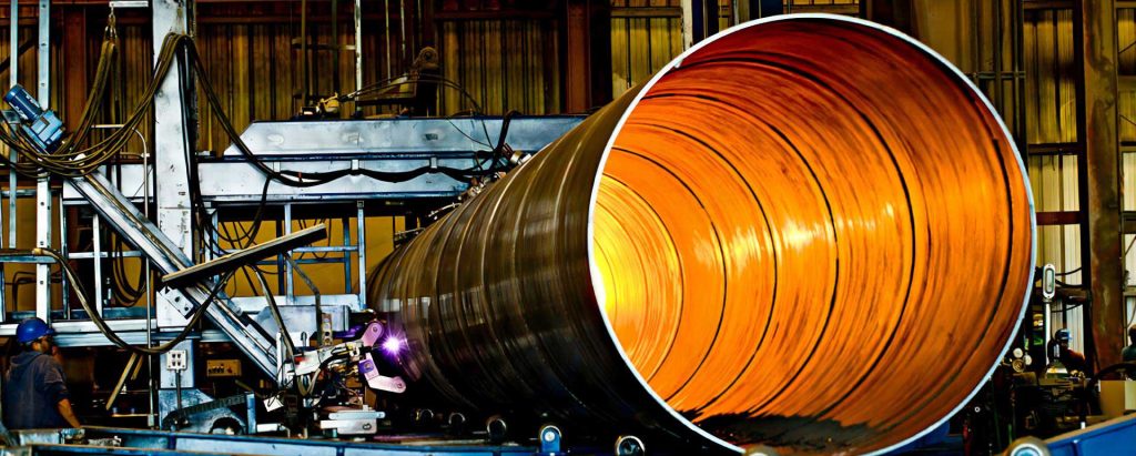
large diameter Rectangular Steel Pipe manufacturing Method – PART 1
November 25, 2023
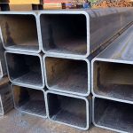
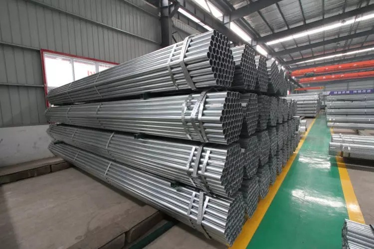
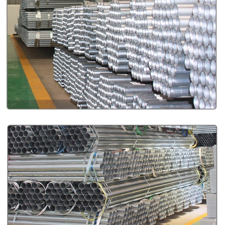
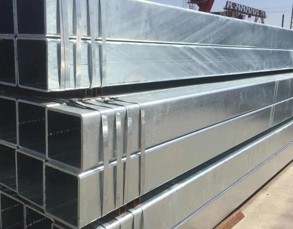
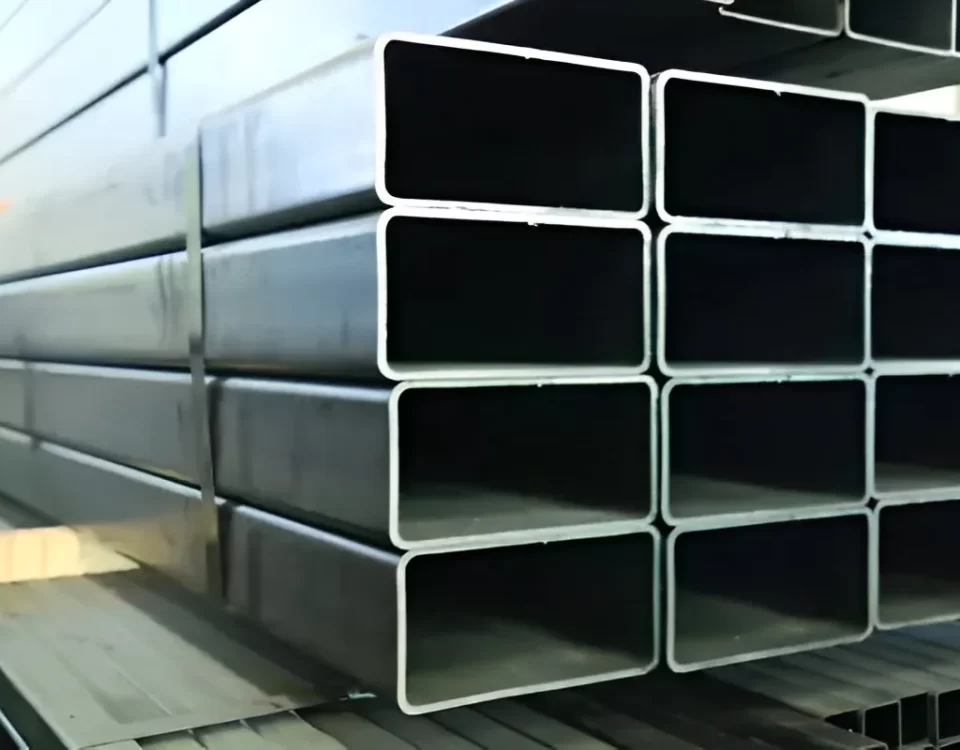
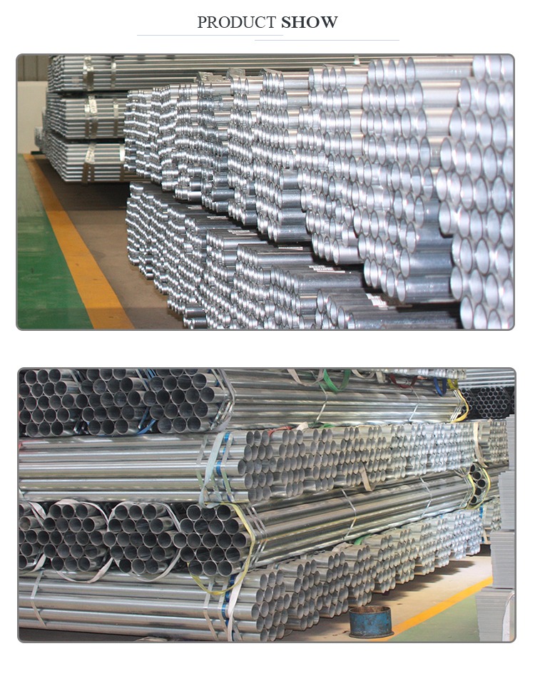
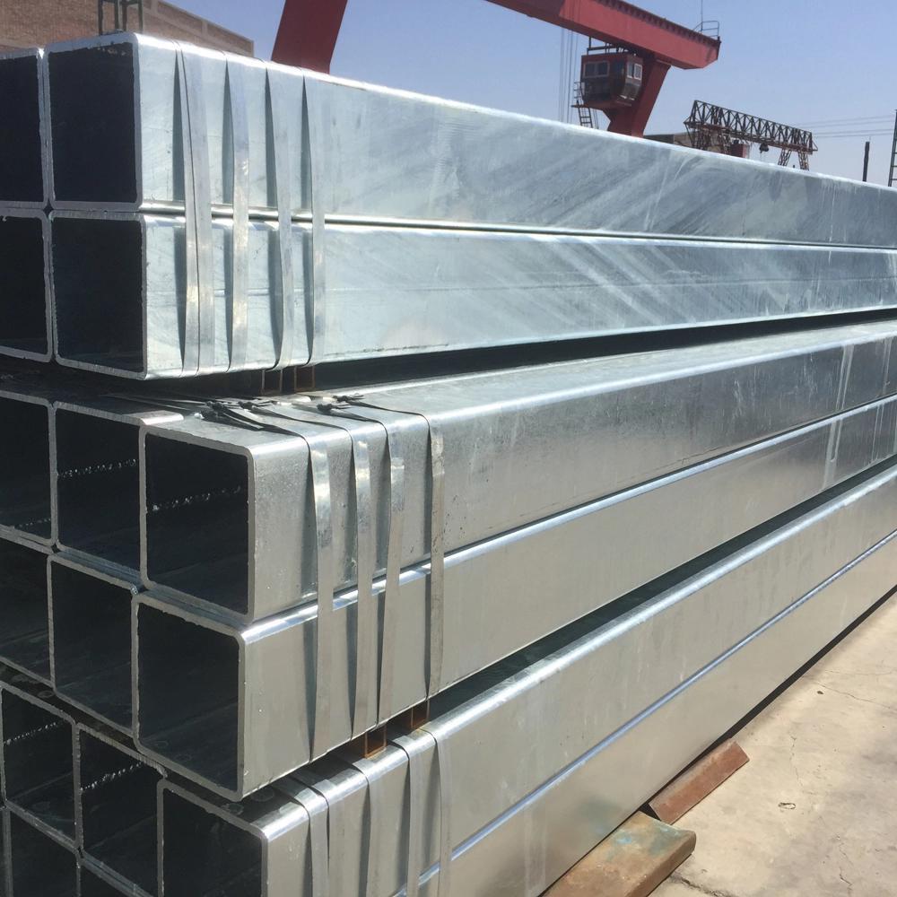
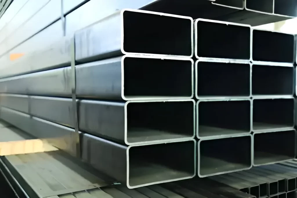
Hollow Section Rectangular and square Steel Pipe for structure
November 25, 2023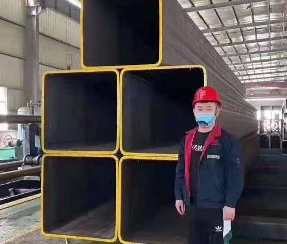
EN10219 Square Hollow Steel Tube: An In-Depth Exploration
| O.D.(mm) | THK(mm) | O.D.(mm) | THK(mm) | O.D.(mm) | THK(mm) | O.D.(mm) | THK(mm) |
| 20*20 | 1.3 | 60*120 80*100 90*90 | 1.50 | 180*180 | 3 | 300*800 400*700 550*550 500*600 | |
| 1.4 | 1.70 | 3.5-3.75 | 9.5-9.75 | ||||
| 1.5 | 1.80 | 4.5-4.75 | 11.5-11.75 | ||||
| 1.7 | 2.00 | 5.5-7.75 | 12-13.75 | ||||
| 1.8 | 2.20 | 9.5-9.75 | 15-50 | ||||
| 2.0 | 2.5-4.0 | 11.5-11.75 | |||||
| 20*30 25*25 | 1.3 | 4.25-4.75 | 12.0-25.0 | ||||
| 1.4 | 5.0-6.3 | 100*300 150*250 200*200 | 2.75 | 300*900 400*800 600*600 500*700 | |||
| 1.5 | 7.5-8 | 3.0-4.0 | 9.5-9.75 | ||||
| 1.7 | 50*150 60*140 80*120 100*100 | 1.50 | 4.5-9.75 | 11.5-11.75 | |||
| 1.8 | 1.70 | 11.5-11.75 | 12-13.75 | ||||
| 2.0 | 2.00 | 12.5-12.75 | 15-50 | ||||
| 2.2 | 2.20 | 13.5-13.75 | |||||
| 2.5-3.0 | 2.5-2.75 | 15.5-30 | |||||
| 20*40 25*40 30*30 30*40 | 1.3 | 3.0-4.75 | 150*300 200*250 | 3.75 | 300*1000 400*900 500*800 600*700 650*650 | ||
| 1.4 | 5.5-6.3 | 4.5-4.75 | |||||
| 1.5 | 7.5-7.75 | 5.5-6.3 | 9.5-9.75 | ||||
| 1.7 | 9.5-9.75 | 7.5-7.75 | 11.5-11.75 | ||||
| 1.8 | 11.5-16 | 9.5-9.75 | 12-13.75 | ||||
| 2.0 | 60*160 80*140 100*120 | 2.50 | 11.5-11.75 | 15-50 | |||
| 2.2 | 2.75 | 13.5-30 | |||||
| 2.5-3.0 | 3.0-4.75 | 200*300 250*250 | 3.75 | 400*1000 500*900 600*800 700*700 | |||
| 3.25-4.0 | 5.5-6.3 | 4.5-4.75 | |||||
| 25*50 30*50 30*60 40*40 40*50 40*60 50*50 | 1.3 | 7.5-7.75 | 5.5-6.3 | 9.5-9.75 | |||
| 1.4 | 9.5-16 | 7.5-7.75 | 11.5-11.75 | ||||
| 1.5 | 75*150 | 2.50 | 9.5-9.75 | 12-13.75 | |||
| 1.7 | 2.75 | 11.5-11.75 | 15-50 | ||||
| 1.8 | 3.0-3.75 | 12-13.75 | |||||
| 2.0 | 4.5-4.75 | 15.5-30 | |||||
| 2.2 | 5.5-6.3 | 200*400 250*350 300*300 | 4.5-6.3 | 500*1000 600*900 700*800 750*750 | |||
| 2.5-3.0 | 7.5-7.75 | 7.5-7.75 | 9.5-9.75 | ||||
| 3.25-4.0 | 9.5-16 | 9.5-9.75 | 11.5-11.75 | ||||
| 4.25-4.75 | 80*160 120*120 | 2.50 | 11.5-11.75 | 12-13.75 | |||
| 5.0-5.75 | 2.75 | 12-13.75 | 15-50 | ||||
| 5.75-6.3 | 3.0-4.75 | 15.5-30 | |||||
| 40*80 50*70 50*80 60*60 | 1.3 | 5.5-6.3 | 200*500 250*450 300*400 350*350 | 5.5-6.3 | 500*1100 600*900 700*800 800*800 | ||
| 1.5 | 7.5-7.75 | 7.5-7.75 | 9.5-9.75 | ||||
| 1.7 | 9.5-9.75 | 9.5-9.75 | 11.5-11.75 | ||||
| 1.8 | 11.5-20 | 11.5-11.75 | 12-13.75 | ||||
| 2.0 | 100*150 | 2.50 | 12-13.75 | 15-50 | |||
| 2.2 | 2.75 | 15.5-30 | |||||
| 2.5-3.0 | 3.0-4.75 | 280*280 | 5.5-6.3 | 600*1100 700*1000 800*900 850*850 | |||
| 3.25-4.0 | 5.5-6.3 | 7.5-7.75 | 9.5-9.75 | ||||
| 4.25-4.75 | 7.5-7.75 | 9.5-9.75 | 11.5-11.75 | ||||
| 5.0-6.0 | 9.5-9.75 | 11.5-11.75 | 12-13.75 | ||||
| 40*100 60*80 70*70 | 1.3 | 11.5-20 | 12-13.75 | 15-50 | |||
| 1.5 | 100*200 120*180 150*150 | 2.50 | 15.5-30 | ||||
| 1.7 | 2.75 | 350*400 300*450 | 7.5-7.75 | 700*1100 800*1000 900*900 | |||
| 1.8 | 3.0-7.75 | 9.5-9.75 | 11.5-11.75 | ||||
| 2.0 | 9.5-9.75 | 11.5-11.75 | 12-13.75 | ||||
| 2.2 | 11.5-20 | 12-13.75 | 15-50 | ||||
| 2.5-3.0 | 100*250 150*200 | 3.00 | 15.5-30 | ||||
| 3.25-4.0 | 3.25-3.75 | 200*600 300*500 400*400 | 7.5-7.75 | 800*1100 900*1000 950*950 | |||
| 4.25-4.75 | 4.25-4.75 | 9.5-9.75 | 11.5-11.75 | ||||
| 5.0-6.3 | 9.5-9.75 | 11.5-11.75 | 12-13.75 | ||||
| 50*100 60*90 60*100 75*75 80*80 | 1.3 | 11.5-11.75 | 12-13.75 | 15-50 | |||
| 1.5 | 12.25 | 15.5-40 | |||||
| 1.7 | 140*140 | 3.0-3.75 | 300*600 400*500 450*450 | 7.5-7.75 | 900*1100 1000*1000 800*1200 | ||
| 1.8 | 4.5-6.3 | 9.5-9.75 | |||||
| 2.0 | 7.5-7.75 | 11.5-11.75 | 20-60 | ||||
| 2.2 | 9.5-9.75 | 12-13.75 | |||||
| 2.5-3.0 | 11.5-25 | 15.5-40 | |||||
| 3.25-4.0 | 160*160 | 3.00 | 400*600 500*500 | 9.5-9.75 | 1100*1000 1100*1100 | ||
| 4.25-4.75 | 3.5-3.75 | 11.5-11.75 | 20-60 | ||||
| 5.0-5.75 | 4.25-7.75 | 12-13.75 | |||||
| 7.5-8 | 9.5-25 | 15.5-40 |
How to make large diameter square tubes, methods and techniques for making square tubes:
0022 In the above forming production line, the steel pipe passes through the equipment from the coiling mechanism 1 to the weld bead removal mechanism 8. The process is almost the same as that of the traditional single-seam resistance welded round pipe steel pipe manufacturing equipment. The steel plate materials used for this are usually thick hot rolled coils (such as STKR41, 50, etc.), and the coil width will limit the maximum diameter of the final product (large diameter rectangular steel pipe) (in the case of single-slit pipes). In the round steel pipe forming process, the thick steel plate (t=16~26m) is deformed by cold plastic processing. Therefore, during the process, due to the above deformation, the material undergoes work hardening and residual stress, and the steel is caused by high-frequency wave welding after forming. Welding deformation, in order to eliminate this problem as much as possible, leave space on the longer section for slow cooling of the steel pipe.
[0023] In the construction method of the present invention, the space required for the slow cooling process of the above-mentioned steel pipe, or this space, is provided with a heating device equipped with a furnace 9 that uses fossil fuel as a heat source and is longer in the conveying direction and high-frequency induction heating. Device 10. Therefore, the production line can be installed without significantly extending the entire length of the production line compared to conventional equipment. There, while the high-frequency welding heated part of the steel has not yet cooled, the steel pipe is transported to the heating device and heated sequentially or gradually over time. Heating the material by heating the steel is also effective in eliminating welding distortion or residual stresses in the steel, so corrections within the heating device may need to be considered. In any case, the energy saving effect can be expected. When the high-frequency heating device 10 is installed at the front stage and the fossil fuel heating furnace is installed at the rear stage, the above effect is also the same.
Figure 2 shows a schematic cross-sectional view perpendicular to the longitudinal axis of the heating furnace 9. In the figure, 18 is the cross-section of the round steel pipe, and 19 is the cross-section of the cross-shaped steel pipe. The guide rollers 20 installed on both sides of the steel pipe in the furnace are the lower guide roller and the conveyor roller, and at least the roller 20 has a circumferential surface. /span> Preferably, due to its wedge shape, the contact area with the steel pipe 18 is wider. The inner wall of the heating furnace 9 is generally made of stacked refractory bricks, and the top is arched. The burner and exhaust arrangement are omitted from the figure. FIG. 3 is a conceptual diagram of a cross-section perpendicular to the axial direction of the high-frequency induction heating device 10. In the picture, 1
0025 If the heating level of the steel pipe 18 is taken into account
, the high-frequency heating device 10 should be installed in the front section of the steel pipe heating process, or A, based on cold plastic processing, etc., to form the peripheral wall of the circular cross-section steel pipe through hot forming. It is extruded from all sides to gradually form a steel pipe with a square cross-section. The residual stress steel plate is removed, the quality is improved, and it is immediately transported to the multi-stage corner forming roller mechanism 11 and heated to near the phase transformation point 3 1 or A
The heat resistance and cooling means of the equipment are relatively easy to consider, with the advantage that it is easier to protect, manage and extend its service life. In this way, the heat-treated round steel pipe
[0026] Figure = 2> or as shown in Figure 7. In the figure, 18′ is the cross section of the steel pipe that has been deformed into a slightly square shape. In Figure 6, the two axes orthogonal to the longitudinal axis of the steel pipe are parallel to each other. The forming rollers 22 and 22′ (parallel to the longitudinal axis of the steel pipe) squeeze the circumferential surface of the circular steel pipe from four directions to form its circumferential surface into a slightly interlocking shape. For example, it goes through eight stages each time from top to bottom, left and right, and then it is shaped into a gradually approaching rectangular cross-section. Each time the steel pipe formed in this way passes through a rolling mill table, its corner radius decreases, and the cross-section of the steel pipe also becomes smaller, approaching a square shape, which is close to the cross-section of the final product. 0027 In Figure 7, the circumferential surfaces fixed on two axes perpendicular to the longitudinal axis of the steel pipe and parallel to each other are deeply connected. The circumferential surface of the round steel pipe is stamped from four pieces. Through the two areas where work hardening of the material has been eliminated, residual stresses and high-frequency welding deformations have been eliminated, other corner areas are also not allowed. The overall residual stress is extremely small, and material degradation is caused by plastic deformation due to thermal processing. In the case of round steel pipes that undergo heat treatment and cold plastic processing, the shaded parts are the two forming rollers 23 and 23′ that constitute the flat surface of the steel pipe. By rotating in the direction, the roller can be shaped into a cross-section gradually approaching a rectangular shape. Figure 8 is a cross-sectional view of a large-diameter square steel pipe formed by a roller mechanism. The characteristics of this hot-formed square steel pipe are as follows: At first glance, the radius of each corner is extremely small. Steel pipe cross-sectional shape (inverted ball shape)
0028] According to the above method, (a) when the round steel pipe is formed into a square cross-section, in the conventional process, the round steel pipe first passes through the sizing machine to make the cross-section a perfect cross-section. However, in the method of the present invention, the steel material softens during hot working, making it easy to manufacture, and since it deforms, it is possible to process round steel pipes with high accuracy without using a sizing machine. (b) When forming a round steel pipe into a rectangular cross-section, in order to obtain an accurate square steel pipe, the temperature of the outer peripheral wall of the round steel pipe must be kept approximately uniform. 7> However, according to this method of the present invention, the entire steel pipe is made of steel A1 or A3. Since it is heated to near the phase transformation point, it is easily deformed, and a square steel pipe with high precision dimensions can be formed.
(c) Due to thermal processing, the corners of the square steel pipe can form a very small radius, and the section modulus of the square steel pipe can be reduced. However, steel pipes have a tendency to soften. The material produced by annealing the steel in the previous process can be recovered through quenching. However, it is necessary to pay attention to the deformation state of the steel pipe due to quenching. (g) The space required for cooling the steel after the square steel pipe is formed can be shortened. , so the material near the corner is less likely to deteriorate. (d) Since it is hot processing, the driving energy of the forming roller mechanism is significantly less than that of cold processing. (e) Since the forming process is simple and does not apply strain to the deformation of the steel plate, distortion of the steel pipe will occur due to the forming process of the square steel pipe. Either it doesn’t happen, or it barely happens. (F) After the square steel pipe is formed, while the heating temperature is high, it can be quickly cooled by evenly blowing cold air or spraying cold water from all sides to reduce the residual stress caused by processing. 0030] (Part 2) In order to eliminate and repair the cold steel pipe. Due to the residual stress and material deterioration a i=2> caused by plastic processing, the heat treatment temperature of the steel plate should be set higher and the treatment time longer, but this will cause the surface of the steel pipe to be rough. 4>This will reduce the commercial value of the final product, and removing it requires shot blasting, sand blasting, etc. , increase costs, increase conditions. In addition, the cost and labor required for heat treatment of steel cannot be ignored. In addition, by setting the heat treatment temperature low, the roughening of the steel plate can be prevented, but the annealing of the material near each corner of the square steel pipe may not be sufficient. Therefore, in the second method of the invention, deterioration due to cold working of the steel material near each corner is considered a special problem in the case of square steel pipe materials. To restore the damage, localized heating is required. Processing is performed near the planned corners of the circumferential wall of the round steel pipe.
0031] However, when the heating temperature of the steel pipe wall is uneven
And when there is a great difference between them, this can = 2> It is known that even if it is installed into the square cross-section forming roller mechanism as shown in Figure 7, a good square cross-section cannot be obtained 4> Therefore, in this implementation In this method, the peripheral wall of the round steel pipe is locally heated, and A1, for example, is used to heat the entire round steel pipe. >Heat uniformly to near the phase change point, adjust the softening degree of the two components to build the peripheral wall of the rectangular steel pipe >Work hardening and heat treatment of flat materials to eliminate residual stress. The uniform heat treatment of the above-mentioned round steel pipe can be carried out using the device shown in Figure 1. However, there is no need to raise the heat treatment temperature until the A3 phase transformation point of the steel material, so the space occupied by the heat treatment equipment is relatively small. 4 and 5 are schematic diagrams of embodiments of a local heating device near a predetermined corner of the peripheral wall of a round steel pipe. /span>So, in this case, electricity is used in both cases. A pair of high frequency heating coils 24, 24′ are connected to the length of the steel pipe 18 in the hand direction in a cross section perpendicular to the central axis of the steel pipe 18, they are mounted symmetrically with respect to said axis and are 90 degrees apart from each other. The pair of coils 24 and the pair of coils 24′ may be mounted slightly offset from each other in the direction of the longitudinal axis of the coils. Steel Pipe. In the figure, the shaded area on the peripheral wall material of the steel pipe portion indicates an area where the temperature is particularly elevated due to local heating. In the case of Figure 5, the frequency applied to the coil 24′ is adjusted so that the inside of the steel pipe can be more heated, and the square steel pipe is formed. At this time, each corner can be deformed more freely and effortlessly, and the shape of the corner R is sharper, which is to obtain a square steel pipe.
The heat source for local heating of the peripheral wall of the steel pipe can of course be a burner using fossil fuels. The round steel pipe after overall heating and partial heating is kept in a heated state through the multi-stage rectangular cross-section forming roller mechanism 11 as shown in the figure. In this mechanism, for example, a high-quality large-diameter rectangular steel pipe as shown in Figure 8 is gradually formed through a multi-stage forming roller as shown in Figure 6 or Figure 7. Subsequent steps are the same as described in the Examples (Part 1).
0034] According to the above construction method, (a) heat the round steel pipe to the material of the steel near the A3 phase transformation point, and perform heat treatment using
At this time, the heat treatment equipment can be made smaller, but the expected effect can be achieved for the same square steel pipe material.
>
and can save fuel and/or electricity consumption
. (b) Other effects achieved by the construction method of this embodiment are substantially the same as those described in embodiment (1).
【0035】
[Effects of the Invention] As described above, according to the construction method of the present invention, it is possible to provide large parts that are conventionally known to be produced by cold plastic processing. By forming the sharpest possible corners, a high-quality steel pipe can be obtained without material degradation. Large-diameter square steel with stable overall quality, work hardening of flat members, and annealing to eliminate internal stress. The quality deterioration is restored. The residual stress has been eliminated to below the allowable level. The corner members of the steel pipe are considered to be problems with rectangular steel pipes.
0036 About heat treatment of steel pipes
During the square steel pipe forming process, when the entire steel pipe is heated, the heat treatment of the square steel pipe
Provides high-quality large-diameter rectangular steel pipes that are easy to form and form sharp corners. Steel pipes with uniform and stable quality can be obtained. In the case of partial heating of the steel pipe (although the entire steel pipe is heated at low temperature), heating energy can be saved compared to what can be achieved. Heat treatment equipment takes up less space. The costs required for heat treatment operations can be reduced to relatively low costs.
0037] When electricity is used as the heating source for heat treatment equipment, (a) the equipment required to heat an object to the required temperature. /span> takes up less space. (b) It is easy to control the temperature of the object to be heated, and (c) a product of stable quality can be obtained. (d) No equipment maintenance is required. (e) Disadvantage is higher electricity bills. (F) Depending on the location, the community’s common capital may not be developed and the required amount of electricity may not be available. In other words, location conditions are limited.
[0038] The cost of heat treatment is lower when using fossil fuels as the heat source. It is relatively easy to obtain and transport in large quantities, regardless of site conditions. Large capacity consumption facilities can be built as needed, but the disadvantage is that the heating facilities take up a lot of space. If the heat treatment equipment is connected in series, the length of the steel pipe forming line will be significantly extended, so the selection of equipment location is important and narrowing of the width is necessary. If we take into account the above-mentioned advantages and disadvantages of using electricity and fossil fuels, and adopt a combined heating method using electricity and fossil fuels, compared to conventionally known heating furnaces, high-performance heat treatment equipment can be installed that can complement each other’s shortcomings . etc., it produces special functions and effects that cannot be expected with known construction methods. . Controlling the required heating temperature is somewhat difficult.