
304L/316 Stainless Steel Butt Welded Reducer
November 6, 2023
SEAMLESS & WELDED STEEL PIPE SUBSTITUTE MATERIAL FOR ASTM STANDARD SPECIFICATION – JIS, BS, DIN
November 11, 2023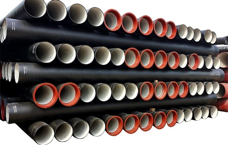
Ductile Iron Water Pipe Systems Examination : Construction, Installation, and Properties
Abstract
This research delves into the design, properties, and installation procedures of Ductile Iron (DI) water pipe systems. Through an in-depth investigation, the study aims to provide a comprehensive understanding of the subject matter, focusing on the major components, their dimensions, handling, and maintenance processes involved in these systems.
Chapter 1: Introduction
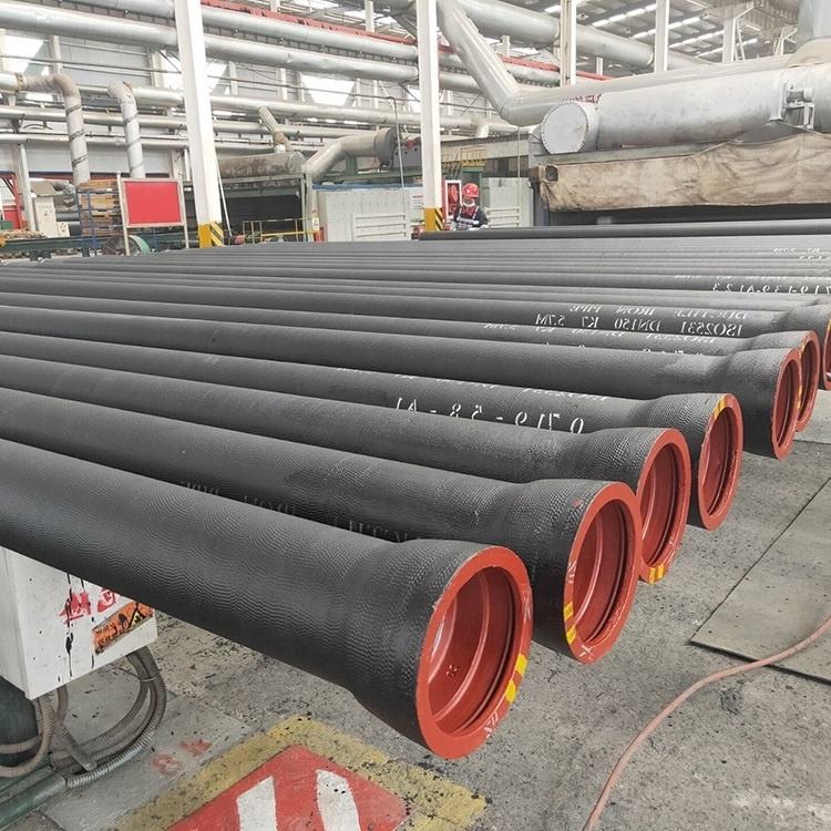
Ductile Iron (DI) water pipe systems form the backbone of water distribution in residential, commercial, and industrial structures. These pressure pipe systems demonstrate adaptability to existing underground or above ground obstructions, making them more flexible than gravity pipe systems. The depth of these water mains and service laterals varies significantly depending on climate conditions and existing obstructions.
Chapter 2: Ductile Iron Water Pipe System Design and Dimension
This chapter elucidates the dimensions and design of DI water pipe systems. It explains that available sizes range from 4″ to 64″, with pipe lengths predominantly being 20′, although 14′ lengths may also be available. The study further investigates the depth placement, indicating that water mains are typically placed at least 6″ below the lowest recorded frost depth.
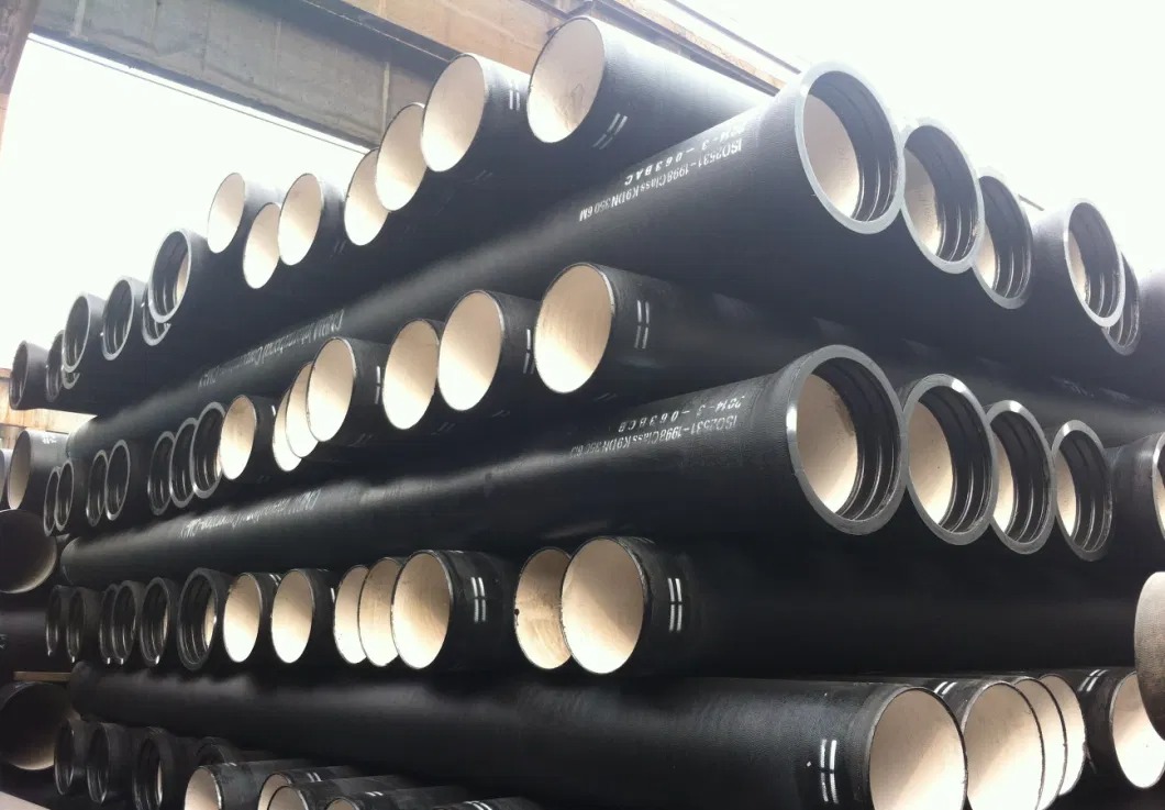
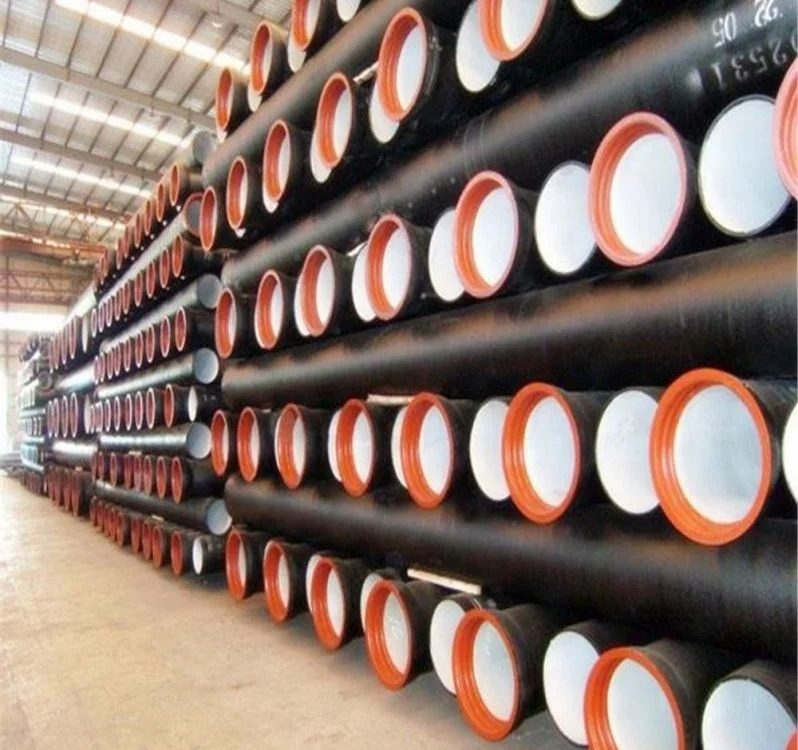
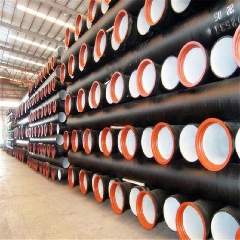
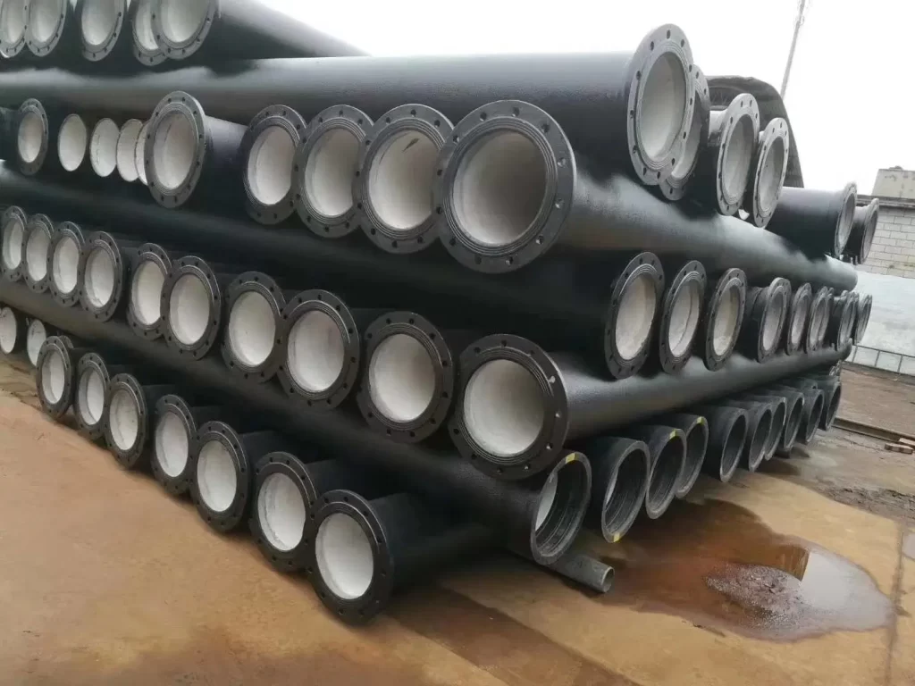
Chapter 3: Properties of Ductile Iron Water Pipes
In this chapter, the properties of DI water pipes are explored. The research underscores that pipe deflection is of negligible concern with ductile iron due to its high strength, unlike plastic water main pipes. Moreover, DI pipes commonly have a cement-lined interior, which contributes to their durability and performance.
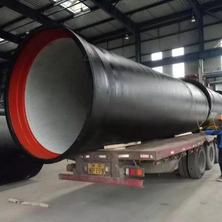

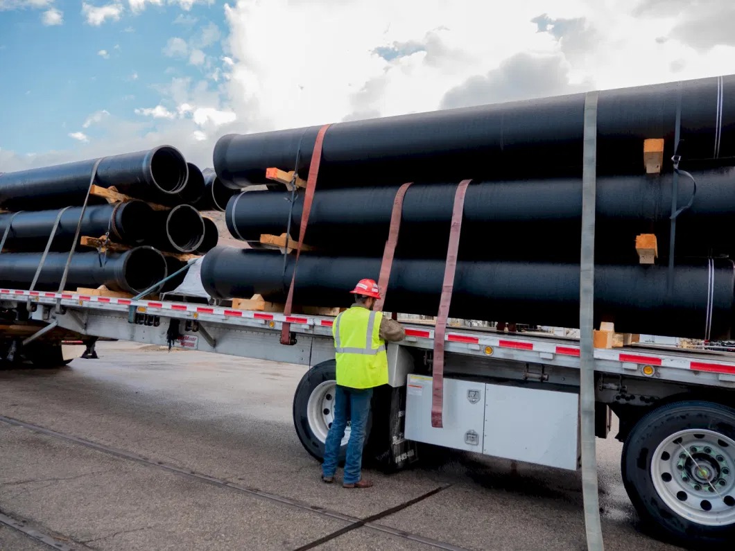
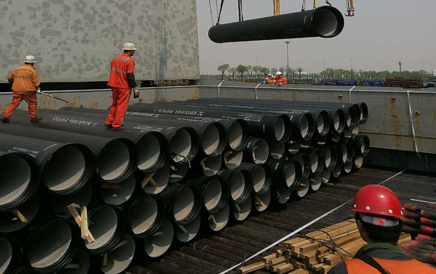
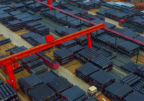
Chapter 4: Handling and Inventory Management of Ductile Iron Water Pipes
This chapter provides insight into the handling and inventory management of DI water pipes. It details the process followed from the moment the delivery truck arrives, including the inspection, inventorying, and unloading processes. The study also discusses the storage and handling precautions to be taken under different weather conditions.
Chapter 5: Installation Procedures: Trench and Cover
This section details the trench and cover installation procedures for DI water pipes. It discusses the trench width determination, the use of ‘full profile’ trench boxes for trench wall shoring, and the methods for replacing larger sections of the pipe. It also outlines the repair procedures for damaged pipes.
Chapter 6: Pipe Jointing Systems in Ductile Iron Water Pipes
This chapter delves into the jointing systems of DI water pipes, explaining the use of molded synthetic rubber gaskets for a water-tight push together jointing system. It elaborates on the installation process, including the cleaning, lubrication, and insertion of the bell, gasket, and spigot. The study highlights that more joint deflection is allowed with DI pipes than plastic pipes.
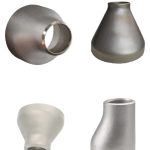
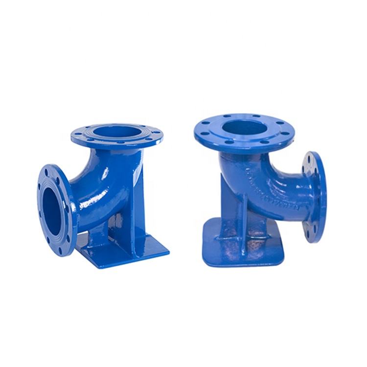
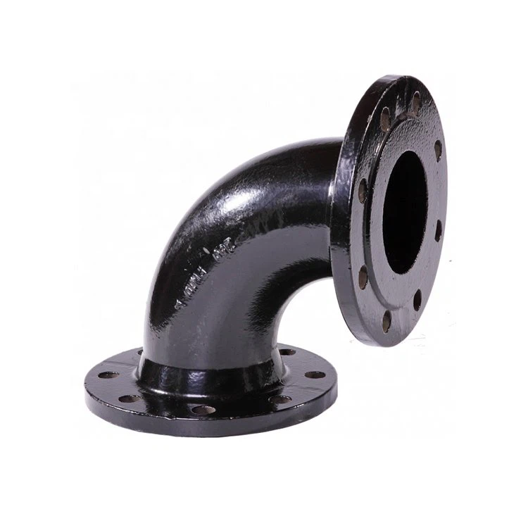
Chapter 7: Fittings in Ductile Iron Water Pipe Systems
The final chapter examines the use of fittings in DI water pipe systems. It discusses the types of fittings available for DI pipes, particularly focusing on ‘Mechanical Joint’ fittings, which are typically available in sizes up to 48” and in working pressures of 150, 250, and 350psi.
Chapter 8: An Examination of Megalugs
In this chapter, the study examines the construction and coating of Megalugs. They are typically used in conjunction with ‘Wedge-Action Restraint’ devices at the joint and are composed of a ‘gland’, torque-limiting bolts/nuts, and ‘T-Bolts/nuts. The chapter also explains the coating of Megalugs for corrosion/impact/UV resistance.
Chapter 9: Installing Megalugs in DI Water Pipe Systems
This chapter delves into the installation process of Megalugs in DI water pipe systems. It provides a step-by-step guide on the installation process, including the preparation of the spigot end, the use of a lubricant, and the tightening of bolts.
Chapter 10: Service Connections in DI Water Pipe Systems
The fourth chapter discusses the assembly required for service connections to the main, focusing on Compression Fittings and Flared Connection. It emphasizes the rule of thumb for ductile iron pipe services and the need for a tapping ‘saddle’.
Chapter 11: Thrust Blocking in DI Water Pipe Systems
This chapter focuses on the necessity of thrust blocking when installing ductile iron pipe and fittings. It explores the use of cast-in-place concrete or precast concrete blocks for thrust blocking and explains the need for additional joint restraint in certain situations.
Chapter 12: Cutting Ductile Iron Pipes
In this chapter, the study examines the cutting process of ductile iron pipes. It provides a comprehensive guide on how to make a ‘square’ cut and the need for a ‘bevel’ to fit into the taper inside the bell. The chapter also discusses the marking of a new insertion or ‘home’ line on the cut end.
Chapter 13: Structure Connections in DI Water Pipe Systems
This chapter focuses on the structure connections in DI water pipe systems, specifically when an in-line valve and manhole are required. The study explores two common connection types: mortared and booted, and explains the circumstances under which each connection is used.
Chapter 14: Backfill Techniques in Ductile Iron Pipe Systems
The final chapter investigates the backfill techniques used in DI water pipe systems. It explains the selection of trench backfill material depending on whether the pipe resides underneath or within the ‘zone-of-influence’ of pavement or a structure foundation.
Conclusion
The study concludes by summarizing the significant findings about the design, properties, and installation procedures of DI water pipe systems. It emphasizes the adaptability, strength, and durability of DI pipes, making them a reliable option for water distribution systems in diverse settings.