
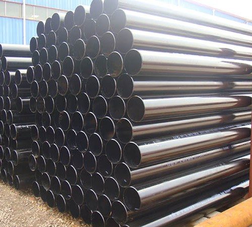
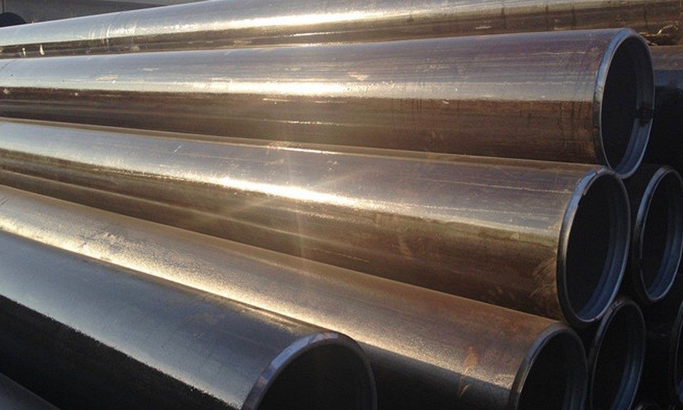
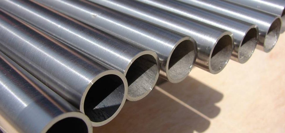
Detailed explanation of Pipe and Tube
December 29, 2021Various inspection methods of oil casing
January 12, 2022Inspection, test
Test equipment
In order to ensure that all products meet the requirements of this standard, the manufacturer shall determine the appropriate calibration frequency for the test equipment.
If the equipment required to be calibrated or verified in accordance with the provisions of this standard is in an abnormal condition or seriously affects its accuracy, the equipment should be recalibrated before being used again.
Definition of mechanical performance test batch
No. 1, 2 (M65, L80 steel grade 1 and C95 steel grade) and group 3—coupling blanks and steel pipes, except for short sections that are cut into semi-finished products or individually reported for heat treatment
A batch is defined as: a part of steel of different heats that is grouped by the same heat or according to the procedures specified in the document and can be guaranteed to meet the corresponding requirements of this international standard after rolling or continuous heat treatment (or batch heat treatment) has the same The size and steel grade pipe composition.
L80 9Cr, L80 13Cr, C90, T95 and Q125—–coupling blanks and steel pipes, except for short sections cut into semi-finished products or single pieces for heat treatment
A batch is defined as: a part of pipes with the same specifications, dimensions and steel grades that are part of the same furnace steel and subjected to continuous heat treatment (or batch heat treatment).
Coupling semi-finished products, pup joints or accessories cut into semi-finished products or single for heat treatment
A batch is defined as: a group of pipe fittings of the same furnace steel, with the same specifications, dimensions and steel grade, and this group of pipe fittings is:
a) Simultaneous batch heat treatment in the same heat treatment furnace, or
b) In the same cycle, continuous heat treatment without interruption, the heat treatment furnace is equipped with a record control instrument to provide a control record of the entire heat treatment process, or
c) Single heat treatment in the same heat treatment furnace, and the continuous heat treatment operation process is less than or equal to 8h.
In addition, for C90, T95 and Q125 steel grades, single heat-treated couplings, sub-joints or accessories with specification code 1 greater than or equal to 9 5/8 casing, the number of one batch should not be more than 30; for specifications smaller than the above specifications The number of tubes in one batch should not be more than 50 pieces.
Chemical composition inspection
Couplings, pup joints and accessories
The chemical composition analysis results of couplings, sub-joints and accessories shall be provided by the manufacturer or processing plant, and the samples shall be taken from pipes or billets.
Melting analysis
For groups 1, 2, and 3, when requested by the purchaser, the manufacturer shall provide a melting analysis report for each heat of steel used to manufacture the pipes and couplings on the order provided. According to the requirements of the purchaser, the results of the quantitative analysis of other elements commonly used by the manufacturer to control mechanical properties shall also be provided.
For steel grade Q125, the manufacturer should provide a melting analysis report for each heat of steel used to manufacture the pipes and couplings on the order. The report should include the results of the quantitative analysis of other elements commonly used by the manufacturer to control mechanical properties.
Finished product analysis
For finished product analysis, it should be performed on the final finished tube, sampling from two tubes in each furnace. Electric welded pipes can be sampled on the steel plate of the pipe.
The finished product analysis should include all the elements listed in Table C.5 or Table E.5, as well as other elements commonly used by the manufacturer to control mechanical properties.
The analysis results of the finished products of groups 1, 2 and 3 shall be provided to the purchaser as required.
The analysis of the fourth component shall be provided to the purchaser.
experiment method
Chemical analysis can use any method commonly used to determine chemical composition, such as spectroscopy, X-ray, atomic absorption, combustion technology or wet analysis. The analytical methods used should have standard traceability. In case of dispute, chemical analysis should be carried out in accordance with ISO/TR9769 or ASTM A751.
Finished product analysis re-inspection-all groups
If the composition analysis results of the two tubes representing a furnace product do not meet the requirements, the manufacturer chooses, or the furnace product is scrapped, or the remaining tubes of the furnace are inspected one by one to determine whether they meet the specified requirements. If only one of the two samples does not meet the specified requirements, it shall be selected by the manufacturer, or the furnace product shall be scrapped, or two other tubes shall be taken from the furnace product for re-inspection. If the two retest samples meet the specified requirements, the furnace product is qualified except for the tube that failed the initial analysis. If one or two re-inspection samples do not meet the specified requirements, they shall be selected by the manufacturer, or the furnace product shall be scrapped, or each remaining tube shall be inspected one by one. When inspecting the remaining tubes of any furnace one by one, only the inspection will not be performed. Qualified elements or elements that need to be inspected. The sampling method for the re-inspection analysis shall be the same as the specified product analysis and sampling method. If specified in the order, all the re-inspection analysis results shall be provided to the purchaser.
Stretching test
Stress relief temperature
In order to require the frequency of tensile testing, when the stress release temperature is 56°C (1000°F) lower than the final tempering temperature, it can be considered that the stress release tempered pipe has not undergone “heat treatment”.
Furnace—Controlled Tensile Test—Group 1, 2, 3
For each heat of steel produced in accordance with this standard, the manufacturer shall conduct a tensile test as a control test for each heat of steel. For electric welded pipes, this kind of controlled tensile test can be selected by the manufacturer or performed on the steel plate blank. Or on the finished pipe.
The furnace-controlled tensile test on a tube can also be used as a product test for this batch of tubes.
Test frequency and sampling location-casing and tubing
The test frequency of all sets of casing and tubing is specified in Table C40 or Table E40.
The steel pipes used for the test shall be randomly selected, and when more than one test is carried out, the sampling method shall ensure that the samples provided can represent the beginning and end of the heat treatment cycle (if applicable) and both ends of the pipe. When performing more than one test, the samples except for thickened tubes can be taken from both ends of one tube, and the other samples should be taken from different steel tubes.
Test frequency and sampling location—–coupling blanks, couplings, pup joints and accessories
Refer to Table C.41 and Table E.41 for the test frequency of coupling blanks and couplings, and refer to Table C.42 or E.42 for the test frequency of pup joints and accessories.
For the first group, the second group (except C90 and T95) and the third group of accessories, when sampling on the bar stock, it is cut from the middle equivalent to the wall thickness of the final product.
For the second group (C90 and T95) and the fourth group, the tensile specimens of the joint blanks, couplings, sub-joints and accessory materials that are heat-treated in the whole tube shall be taken according to Figure D.10.
For short sections or accessories manufactured with previously tested and qualified casing, tubing or coupling semi-finished products, if no subsequent heat treatment is performed, then no tensile test shall be performed.
Furnace—Controlled tensile test can also be used as a product test of this batch of pipes.
Sample—–General
The tube tensile specimen can be selected by the manufacturer, either a full-section specimen, a strip specimen, or a round rod specimen, as shown in Figure D.9. The strip specimens taken from the seamless pipe and coupling blanks can be determined by the manufacturer. Taken from any position on the circumference of the pipe. The round bar sample should be taken from the middle of the tube wall. The strip specimens and round rod specimens taken from the electric welded pipe should be taken at a position about 90º from the weld, or selected by the manufacturer, on the steel plate for pipe making, parallel to the rolling direction and about four minutes away from the edge of the plate. Sampling at one of the widths of the steel strip. The tensile test specimens of heat-treated steel pipes and coupling materials should be taken from the final heat-treated pipes on the production line.
If a test fixture with a suitable curved surface can be used, or both ends of the sample can be machined or cold pressed to reduce the curvature of the clamping surface, the width within the gauge length of all strip samples is about 38mm (1.500in ). Otherwise, for the pipe with specification code 1 less than 4, the width of the sample gauge length is about 19mm (0.75in); for the pipe with specification code 1 of 4~7 5/8 specifications, its width is approximately 25mm (1.00in) ); For pipes larger than 7 5/8, the width is about 38mm (1.500in).
Except for round rod samples, all tensile samples of the tube body shall represent the entire wall thickness of the intercepted tube, and the samples shall not be flattened during the test. If a round rod sample is used, when the tube size allows, a 12.7mm (0.500in) diameter sample shall be used; for other specifications, a round rod sample with a diameter of 8.9mm (0.350in) shall be used. When the size of the tube is too small to take the 8.9mm (0.350in) sample, the round rod tensile sample is not applicable. When it is necessary to record or report the elongation, the record and report should report the specified width of the strip sample used, or the diameter and gauge length of the round bar sample used, or the condition of the full-section tubular sample used.
10.4.6 Specimen-Additional requirements for Q125 steel grade couplings, pup joints and accessories
In addition to the requirements in Section 10.4.5, longitudinal tensile test specimens shall be taken from the coupling, sub-joint or accessory material. For the semi-finished coupling, sub-joint or accessory that undergoes separate heat treatment, it shall be taken after the final heat treatment. The tensile specimen shall be a strip specimen, or when the tube wall thickness is greater than 19.1mm (0.750in), a round bar specimen with a diameter of 12.7mm (0.500in) as shown in Figure D.9 may be used.
For couplings, pup joints or accessory materials that are heat-treated with coupling semi-finished products or a single piece, the tensile test specimens shall be cut as shown in Figure D.10.
According to the agreement between the supplier and the buyer, a strip sample with a small cross-section can be used.
experiment method
The tensile properties of the product should be measured on a longitudinal sample. The sample should meet the requirements of Section 10.4.5, ISO6892 or ASTM A370. Q125 steel grade products should meet the requirements of Section 10.4.6. The tensile test should be carried out at room temperature. The strain rate during the tensile test should meet the requirements of ISO6892 or ASTM A370.
The tensile testing machine shall be calibrated to ISO 7500-1 or ASTM E4 within 15 months before any test. The extensometer shall be calibrated according to ASTM E83 within 15 months before any test. Records should be kept in accordance with the provisions of 13.5.
Test invalid
If any tensile test specimen is machined unqualified or defective, the test specimen can be scrapped and replaced by another test specimen.
Re-inspection-all products except C90, T95 and Q125 steel grade couplings, coupling blanks, sub-joints and accessories
If one tensile test specimen representing a batch of tubes does not meet the specified requirements, the manufacturer can take three other tubes from the same batch for re-inspection.
If all the re-inspected samples meet the requirements, the batch of steel pipes will be judged as qualified except for the unqualified pipe that was originally sampled.
If more than one sample in the initial test does not meet the specified requirements or one or more samples in the re-test sample do not meet the specified requirements, the manufacturer may inspect the remaining steel pipes of the batch one by one. The sampling method for retest samples shall be the same as specified in 10.4.5 and 10.4.6. The retest specimens of steel grades M65, L80 and C95 shall be taken from the same end of the original specimen.
The unqualified batch can be heat treated again and retested as a new batch of tubes.
Re-inspection—–C90, T95 and Q125 steel grade couplings, coupling blanks, pup joints and accessories
For materials heat-treated in the whole tube, if a tensile test specimen does not meet the specified requirements, the manufacturer shall sample and test the problematic steel tube at both ends or scrap the steel tube. No additional tests are allowed to determine whether the coupling, sub or accessory materials are qualified. Both samples should meet the specified requirements, otherwise the steel pipe will be rejected. The manufacturer can re-heat the batch of waste pipes and re-test as a batch of pipes.
For materials that are heat-treated with coupling semi-finished products or single products, if a tensile test does not meet the specified requirements, the manufacturer should re-heat the batch of tubes in question, or take another three from the batch of tubes in question. Test each sample. If one or more samples do not meet the requirements, the batch of tubes shall be scrapped. The manufacturer can re-heat the batch of waste pipes and re-test as a new batch of pipes.
Flattening test
General requirements for testing
All welded pipes with the D/t ratio shown in Tables C.23 and E.23 shall be subjected to a flattening test.
In Sections 10.5.2 to 10.5.7, the 0º position refers to the weld contacting the pressure plate (defined as the 12 o’clock or 6 o’clock position), and the 90º position refers to the weld at the 3 o’clock or 9 o’clock position.
Test frequency
The test frequency should be determined in accordance with Table C.44 or E.44.
Sample
The sample should be a sample ring or end cut with a length of not less than 63.5mm (2-1/2in).
For pipes cut from a multi-length coil, the test at one end of the pipe shall represent the subsequent test of the pipe and its adjacent end. If the pipe needs to be thickened, the sample should be taken before the pipe is thickened.
The sample can be cut before the heat treatment, but it must be subjected to the same heat treatment as the representative tube. If batch testing is used, measures should be taken to identify the relationship between the sample and the sampling tube. Each furnace in each batch shall be subjected to a flattening test.
The normalized electric welded pipe of the whole pipe, including the electric welded pipe processed by hot tension rolling according to the requirements of Section 6.2.1, the flattening test can be selected by the production, and it shall be intercepted before or after the heat treatment.
Test method—–group 1 non-integral heat-treated steel pipe
The specimen shall be flattened between two parallel plates. In each group of flattening test specimens, one weld is flattened at the 90° position, and the other is flattened at the 0° position. The sample should be flattened until the tube walls are in relative contact. Before the distance between the parallel plates is less than the value specified in Table C.23 or E.23, no cracks or breaks should occur in any part of the sample. During the entire flattening process, there should be no bad structure, unfused welds, delamination, metal overburning, or metal extrusion.
Test method—–group 1 and 2 integral heat-treated steel pipes
The sample is flattened between two parallel plates, and the weld should be at the largest bend; it is up to the inspector to determine that the weld and the largest bend should be at a position of 90º for flattening test. The sample should be squashed until it touches the tube wall. Before the distance between parallel plates is less than the provisions of Table C.23 or E.23,
There should be no cracks or breaks in any part of the specimen. During the entire flattening process, there should be no bad structure, unfused welds, delamination, metal overburning, or metal extrusion.
Test method—–P110 steel grade pipe and Q125 steel grade casing
When the buyer specifies ERW (electric welding resistance) and SR11, the requirements of A.6 (SR11) shall be implemented.
recheck
If any sample on behalf of a tube does not meet the specified requirements, the manufacturer can take samples from the same end of the tube for supplementary tests until the requirements are met. However, the length of the finished tube after sampling shall not be less than 80% of the original length. If any sample of a tube representing a batch of products does not meet the specified requirements, the manufacturer can take another two tubes from the batch of products. Sample re-inspection. If these re-inspection results meet the specified requirements, the batch of tubes will be qualified except for the tube originally selected as the sample. If any sample for re-inspection does not meet the specified requirements, the manufacturer can take samples from the remaining tubes of the batch one by one. The sampling method for re-inspection is the same as specified in 10.5.3. Any batch of tubes can be re-heat treated as selected by the manufacturer and re-tested as a new batch of tubes.
Hardness test
PSL requirements
Test frequency—–general
The hardness test frequency of all products is shown in Tables C.43 and E.43.
The supplier and the buyer agree that the steel pipe and the thickened part can be subjected to the additional hardness test of the outer surface and the hardness test of the full wall thickness. The test method of this additional test shall be agreed between the supplier and the buyer.
For puppies or accessories processed from tested M65, L80, C90, T95 or Q125 steel grade puppets or accessories, if there is no subsequent heat treatment, hardness test is not required.
Test frequency-Furnace-Control test-M65 and L80 steel grade
Taken from each furnace-the hardness test specimens of the controlled tensile test specimens shall undergo a full wall thickness hardness test to determine whether they meet the hardness requirements.
The furnace-control test carried out on a tube can also be used as a product test for this batch of tubes.
Test frequency—–M65 and L80 steel grade
For steel pipes, couplings and accessory materials, the frequency of the hardness test should be the same as the frequency of the corresponding tensile test for each product.
Test frequency and sampling location—–non-thickened pipe—–C90 and T95 steel grade
For non-thickened pipes, a full wall thickness hardness test should be carried out in one quadrant. The sample should be taken from one end of each pipe. About 50% of the sample ring should be taken from the front end of the pipe and the other half should be taken from the pipe. The back end.
Test frequency and sampling location—–thickened pipe—–C90 and T95 steel grade
The full wall thickness hardness test shall be carried out in the four quadrants of the tube body of each tube after the tensile test according to the requirements of 10.4.3 to determine whether it meets the requirements. The test frequency of upset pipes should be every 20 pieces in each batch. The specimen shall be taken from the thickest part with the largest wall thickness, and a full wall thickness hardness test shall be carried out in the four quadrants.
In addition to the hardness test of the full wall thickness (cross-section), the Brinell hardness or Rockwell hardness test shall be carried out on the outer surface of the tube body and the thickened part of each tube.
Test frequency and sampling location—–couplings, sub-joints and accessories—–C90 and T95 steel grades
For thick-walled pipes used to produce more than one coupling, sub-joint and accessories, one sample ring shall be taken at each end of the steel pipe, and both sample rings shall be subjected to the full-wall thickness hardness test.
For single heat-treated couplings, sub-joints and accessories, the pipe fittings with the largest surface hardness in the batch should be selected for testing.
For a single heat-treated coupling, the hardness test ring shall be cut from the middle as shown in Figure D.10. For single heat-treated pup joints and accessories, for couplings, puppies or accessories heat-treated using the method c) specified in 10.2.3, the hardness test ring can be cut from the middle as shown in Figure D.10, or from The extended part is intercepted.
The full wall thickness hardness test should be carried out in the four quadrants.
Test frequency—–Q125 steel grade
For casing, 3 pipes from each batch are tested for full wall thickness hardness. If the sampling method can ensure that the provided samples can represent the beginning and end of the heat treatment cycle and both ends of the tube, the test tube should be randomly selected.
For couplings, sub-joints or accessory materials that are heat-treated in the whole pipe, one end of each pipe shall be subjected to a full wall thickness hardness test (each end shall have a 50% sampling probability).
For couplings, sub-joints or accessories that are semi-finished or single heat-treated couplings, one sample shall be taken from each batch for the full wall thickness hardness test.
The full wall thickness test shall be performed in one quadrant.
For PSL-3 products, see Appendix H for additional requirements.
Sample
The hardness sample should be taken from the product at the position shown in Figure D.10, or taken from the pipe end or extension according to the provisions of this standard. For all steel grades, the full wall thickness hardness test shall be carried out on the test ring or test block.
For the full wall thickness hardness test of one quadrant, it shall be carried out on the specimen block taken from the specimen ring or tensile specimen. For the full wall thickness hardness test of the four quadrants, it shall be carried out on the sample ring or the sample block taken from the sample ring. The full wall thickness hardness test ring shall be prepared in accordance with Figure D.11.
The two surfaces of the hardness sample should be ground parallel and smooth, and there should be no oxide scale, impurities and lubricant on the surface of the hardness sample.
experiment method
The Brinell hardness test should be carried out in accordance with ISO6506-1 or ASTM E10, and the Rockwell hardness should be carried out in accordance with ISO6508-1 or ASTM E18.
In this standard, two test methods are used:
a) The outer surface test includes an indentation;
b) The full wall thickness hardness test includes multiple indentations.
The outer surface hardness test can be carried out by either the Rockwell hardness method or the Brinell hardness method. It is stipulated in this standard that the external surface hardness test is used for product determination and process control.
The full wall thickness hardness test should be tested according to the Rockwell hardness method, and used to determine the maximum hardness, the allowable quantification of the hardness change, and the hardenability of the quenched state. The hardness test of the full wall thickness should be carried out perpendicular to the axis of the steel pipe. When the sample ring is cut from the pipe end, the hardness test should be carried out from the side of the sample ring away from the pipe end (that is, away from the quenched end surface). In order to reduce possible errors, the first hardness indentation of the first quadrant of each hardness test block or sample ring can be omitted.
When the specified wall thickness is less than 7.62mm (0.30in), for the full wall thickness hardness test, 3 indentations in the middle of the sample wall thickness shall be taken. For all other products, the 3 indentations in each quadrant should be in three positions. The hardness readings of 3 indentations in each position (such as outer, middle and inner), the average value of which is the average hardness reading of that position. The full wall thickness hardness test consists of the average hardness readings of each position in one quadrant. Whether the full wall thickness hardness test is carried out in one quadrant or four quadrants should be calibrated in accordance with this standard.
The inner and outer indentation should be measured in a tape 2.54-3.18mm from the surface, but the distance between the center of the indentation and the inner and outer surfaces should not be less than 2½ times the diameter of the indentation. The distance between the indentations should be at least 3 times the indentation diameter (from the center of the indentation to the center of the indentation). For thin-walled tubes, the spacing between each row is allowed to be staggered.
The Rockwell C scale method is generally used for the full wall thickness test. Materials with hardness less than 20HRC shall be accepted by Rockwell C scale method. When the measured hardness is lower than 20HRC, it should be used with care due to the reduced accuracy, but these results can be used to determine the hardness. It is selected by the manufacturer or specified by the purchaser that the Rockwell B scale method can be used for materials with a hardness lower than 20HRC. Rockwell hardness readings and average hardness readings should be reported on the Rockwell C scale, accurate to one decimal place. When the order stipulates in A.9 (SR15), the manufacturer shall provide three readings to the purchaser.
Unless agreed by the purchaser, the hardness conversion should be selected by the manufacturer and converted according to an appropriate conversion table.
The Brinell hardness reading should be rounded to three significant digits. When the test pressure is greater than 29.342kN (3000kgf), the pressure ball diameter is greater than 10mm, and the test pressure lasts for 10s~15s, the test conditions should be reported.
In case of dispute, the hardness test of the HRC scale in the laboratory shall be used as the stretching method.
Test invalid
If any hardness test specimen is unqualified or defective in machining, the test specimen can be scrapped and replaced by another test specimen.
Periodic calibration of hardness testing machine
The Brinell hardness testing machine should be periodically verified according to ISO6506-1 or ASTM E18 Part B steps, and the Rockwell hardness tester should be periodically verified according to ISO6508-1 or ASTM E10 Part B steps; the ISO title is “Regular User Verification” The part of the “Procedures of the Testing Machine” and the chapter of ASTM titled “Regular User Verification Procedures” are interrelated. At the beginning and end of the continuous operation process of the testing machine, the test should be verified as many times as required so that the manufacturer, purchaser (or its representative) can confirm that the testing machine is within the calibration range. Use the following standard test blocks for the hardness range for verification:
a) The second group: 20HRC~35HRC
b) Q125 steel grade: 25HRC~35HRC
If the test result of the testing machine is not within the calibration range, for the Brinell hardness testing machine, the standard test block should be indirectly verified according to ISO6506-2 or ASTM E18 Part B. For the Rockwell hardness testing machine, the standard test block should be used according to ISO6508-2. Or ASTM E10 Part B indirect verification.
Re-inspection—–M65 and L80 steel grade
For products of M65 and L80 steel grades, if a full-wall thickness hardness sample representing a batch of steel pipes does not meet the specified requirements, the manufacturer can take two more samples from the same batch and the same end of the original sample for re-inspection. If all the re-inspected samples meet the requirements, the batch of steel pipes will be judged as qualified except for the unqualified pipe that was originally sampled. If one or more of the re-inspected samples does not meet the specified requirements, the manufacturer can inspect the remaining steel pipes one by one or reject the entire batch.
Re-inspection—–In addition to the coupling semi-finished products, sub-joints or accessories that are cut into a single piece for heat treatment, other products of C90 and T95 steel grades
For C90 and T95 steel grades, if any of the average hardness readings is between 25.4HRC and 27.0HRC (including 27.0HRC), then three more hardness readings should be measured in the closest area to determine a new average hardness reading . If the new average hardness reading does not exceed 25.4HRC, the tube is qualified. If the new average hardness reading exceeds 25.4HRC, the root canal should be scrapped.
Re-inspection—–C90 and T95 steel grades are cut into single coupling semi-finished products, short sections or accessories for heat treatment
For C90 and T95 steel grades that are cut into single pieces for heat treatment of coupling semi-finished products, short sections or accessories, if one hardness sample representing a batch of steel pipes does not meet the specified requirements, the steel pipe shall be deemed as scrap. For the batch of steel pipes selected for the initial inspection, the manufacturer should reheat the batch of steel pipes or use the same selection criteria to take three new samples for testing. If any one of the three retest samples does not meet the specified requirements, the entire heat treatment shall be rejected.
Re-inspection—–Q125 steel grade—–general
If the allowable hardness change on a sample exceeds the provisions of C.6 or Table E.6, the hardness indentation in this quadrant can be removed (selected by the manufacturer), and the indentation in the first test is placed on the lower surface Try again. Each sample is allowed to be reground and retested only once. After re-inspection, products that do not meet the requirements shall be scrapped.
Re-inspection—–Q125 steel grade—–casing
If more than one of the first three test tubes representing a batch of casing fails, the manufacturer may choose to test the remaining tubes of the batch one by one. When these tubes are retested, they are only allowed to be carried out in accordance with Section 10.6.16.
If only one of the first 3 test tubes representing a batch of casing fails. You can take another 3 tubes for re-inspection to determine whether the batch of casing is qualified. During the re-inspection, it is only allowed to be carried out in accordance with the provisions of Section 10.6.16. If any one of the three retested tubes is unqualified, the manufacturer can choose to test the batch of remaining tubes one by one, or reprocess the batch of tubes (that is, for a batch of casing, 6 tubes There must be 5 tubes in the test tube that meet the requirements of Section 7.8 and Table C.6 or E.6 in order to prove that the batch of casing is qualified).
Re-inspection—–Q125 steel grade—–couplings, pup joints and accessories
When couplings, sub-joints or accessories are heat-treated with coupling semi-finished products or single pipes, if the hardness change specified in Section 7.8 exceeds the value specified in Table C.6 or E.6, the manufacturer can select it from the batch. Take another 3 of the products for full wall thickness hardness re-inspection. If any one of the 3 retested products does not meet the maximum hardness change value, the batch of products shall be scrapped.
The whole critique is abolished—–group 2 and group 4
For all products, the entire batch of waste steel pipes should be reprocessed (ie, re-heat treatment), and the hardness test should be repeated as a new batch.
