Alloy B, UNS N1001 stainless steel pipe and fittings
September 26, 2026
Petrochemical Industry
Welding of N08825+Q245R Clad Pipe
1. Overview
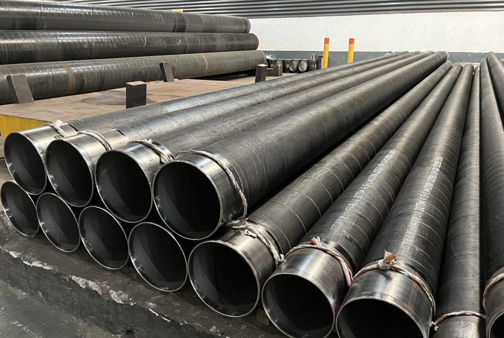
In a chemical plant constructed by our company, 1447m of N08825+Q245R clad steel rolled pipes were used, with wall thickness ranging from (3+6) to (3+12) mm. Taking the wall thickness of (3+12) mm as an example, the manufacturing standard for the raw materials of the clad rolled pipe is NB/T47002 “Explosive Welded Clad Steel Plates for Pressure Vessels”, and its mechanical properties are shown in Table 1.
Among them, the chemical composition and mechanical properties of the cladding layer are shown in Table 2 and Table 3; the manufacturing standard of the base layer Q245R is GB713 “Steel Plates for Boilers and Pressure Vessels”, and its chemical composition and mechanical properties are shown in Table 4 and Table 5 respectively. The cladding layer B424 N08825 is an iron-nickel alloy with an austenitic metallographic structure. Impurity elements such as S and P easily form low-melting-point eutectics during weld solidification, which may produce hot cracks; at the same time, liquid metal fluidity is poor.
| Mechanical Properties | Tensile Strength / MPa | Temperature / ℃ | Impact Test Impact Absorbed Energy / J |
|---|---|---|---|
| Standard Value | >437.2 | 0 | ≥31 |
| N08825+Q245R | 451 | 0 | 210 |
| Element | C | Fe | Cr | Ni | Mn | Cu | Si | S | Al | Ti | Mo |
|---|---|---|---|---|---|---|---|---|---|---|---|
| Standard Value | ≤0.05 | 19.5 | 38.0 | ≤1.0 | 1.5 | ≤0.5 | ≤0.03 | ≤0.2 | 0.6 | 2.5 | |
| 22.0 | 46.0 | 3.0 | 1.2 | 3.5 | |||||||
| B424 N08825 | 0.01 | 30.9 | 23.1 | 39.3 | 0.4 | 2.2 | 0.3 | 0.001 | 0.1 | 0.7 | 3.1 |
| Mechanical Properties | Tensile Strength / MPa | Yield Strength / MPa |
|---|---|---|
| Standard Value | ≥586 | >241 |
| B424 N08825 | 631 | 298 |
| Element | C | Mn | Si | S | P | Alt |
|---|---|---|---|---|---|---|
| Standard Value | ≤0.20 | 0.5-1.0 | ≤0.35 | ≤0.035 | ≤0.025 | ≥0.02 |
| Q245R | 0.14 | 0.75 | 0.16 | 0.004 | 0.009 | 0.029 |
| Mechanical Properties | Tensile Strength / MPa | Temperature / ℃ | Impact Test Impact Absorbed Energy / J |
|---|---|---|---|
| Standard Value | 400-520 | 0 | ≥31 |
| Q245R | 441 | 0 | 176 |
2. Test Procedure
(1) The welding method adopts manual tungsten inert gas arc welding (GTAW) for root pass, and shielded metal arc welding (SMAW) for capping pass.
(2) Nickel-based welding materials are used for filling, namely welding wire ERNiCrMo-3, Φ2.4mm; welding electrode ENiCrMo-3, Φ3.2mm, with electrode diameter ≤3.2mm. Their chemical composition requirements are shown in Table 6 and Table 7 respectively.
| Element | C | Fe | Cr | Ni | Mn | Cu | Si | P | S | Al | Ti | Nb+Ta | Mo | Others |
|---|---|---|---|---|---|---|---|---|---|---|---|---|---|---|
| Standard | ≤0.10 | ≤5.0 | 20.0~23.0 | ≥58 | ≤0.50 | ≤0.50 | ≤0.50 | ≤0.02 | ≤0.015 | ≤0.40 | ≤0.40 | 3.15~4.15 | 8.0~10.0 | ≤0.50 |
| ERNiCrMo-3 | 0.012 | 0.450 | 21.770 | 64.420 | 0.120 | 0.080 | 0.120 | 0.007 | 0.001 | 0.110 | 0.150 | 3.710 | 8.710 | – |
| Element | C | Fe | Cr | Ni | Mn | Cu | Si | P | S | Co | Nb+Ta | Mo | Others |
|---|---|---|---|---|---|---|---|---|---|---|---|---|---|
| Standard | ≤0.10 | ≤7.0 | 20.0~23.0 | ≥55 | ≤1.0 | ≤0.50 | ≤0.50 | ≤0.03 | ≤0.02 | ≤0.12 | 3.15~4.15 | 8.0~10.0 | ≤0.50 |
| ENiCrMo-3 | 0.030 | 3.01 | 21.37 | 61.96 | 0.65 | 0.04 | 0.46 | 0.012 | 0.003 | 0.10 | 3.21 | 9.07 | <0.5 |
(3) Bevel type: The groove preparation geometry is as shown in the attached diagram (Bevel angle 60°~70°, root face 0.5~1.0mm, root gap 3~4mm).
(4) Welding parameters: Pay attention to the following during welding: ① Groove must be clean to avoid oil contamination. ② Ensure argon purity of 99.99% and provide adequate shielding. ③ Do not weave during welding; run straight beads. ④ Strictly control interpass temperature <100℃. ⑤ Fill the crater when extinguishing the arc, and grind away the arc termination area. Specific welding parameters are shown in Table 8.
| Weld Layer | Welding Method | Polarity | Welding Current / A | Arc Voltage / V | Welding Speed / (cm·min⁻¹) | Argon Flow Rate / (L·min⁻¹) | |
|---|---|---|---|---|---|---|---|
| Front | Back | ||||||
| 1~2 | GTAW | DCEN | 95-105 | 12-14 | 6-8 | 10-12 | 10-12 |
| 3~8 | SMAW | DCEP | 105-110 | 22-24 | 13-20 | – | – |
(5) Welding Procedure Qualification: Test plates welded according to the above requirements were evaluated for joint quality using the qualification method of NB/T47014-2011 “Welding Procedure Qualification for Pressure Equipment”. The radiographic testing results met the Class I quality standard in JB4730 “Nondestructive Testing of Pressure Equipment”. The mechanical properties and bend test results are shown in Table 9. As can be seen from Table 9, the joints welded by the above process are fully qualified according to NB/T47014-2011 “Welding Procedure Qualification for Pressure Equipment”, and reliable quality welded joints can be obtained.
| Tensile Test (GB/T228) | Impact Test (GB/T229) Specimen Spec.: 10mm × 10mm × 55mm Room Temp.: 20℃ | Bend Test (GB/T232) Specimen Spec.: 300mm × 15mm × 10mm D=4S, 180° Side Bend | ||
|---|---|---|---|---|
| Specimen Size / (mm × mm) | Rm / MPa Fracture Location | Heat Affected Zone | Weld | |
| 20.9 x 14.9 | 541 Base Metal | 176 | 95 | Qualified |
| 20.8 x 14.8 | 546 Base Metal | 90 | 144 | Qualified |
| – | – | 95 | 134 | Qualified |
| – | – | – | – | Qualified |
3. Conclusion / Discussion
The joints welded by the above process were continuously boiled for 24h in sulfuric acid-copper sulfate solution according to GB/T15260 “Test Methods for Intergranular Corrosion of Nickel Alloy”. After bending 180° with a 5mm punch, observation under a 10x magnifying glass showed no intergranular corrosion tendency, fully satisfying the corrosion resistance requirements of the weld. The N08825+Q245R clad pipeline welded by this method was put into operation in 2013, and has been running well so far without any quality problems.
Figure 9 shows the pitting test results of curved specimens. From the pitting test results conducted by multiple construction units participating in this project, edge corrosion phenomena exist to varying degrees. If “no corrosion pits on specimen surface” is taken as the qualification criterion, it is indeed overly harsh. For this project, whether “the weld should have corrosion resistance equal to or higher than the inner corrosion-resistant alloy base metal” can be used as the pitting test qualification standard still requires joint discussion among design, construction, manufacturer, and inspection units.
Through the above tests, the following conclusions can be drawn: ① Pitting test for iron-nickel alloy clad pipes places high requirements on specimen machining, and misalignment issues must be considered during sampling. ② Appropriately reducing specimen thickness helps reduce the probability of residual carbon steel layer and prevents corrosion. ③ Due to the influence of the outer carbon steel layer of the clad pipe, edge corrosion is difficult to eliminate; whether corrosion appears cannot be used as the sole evaluation index. ④ It is considered reasonable to evaluate based on whether pitting corrosion appears in the welded joint itself.