
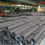
JIS G 4105 SCM420 Seamless Steel Pipe
May 30, 2026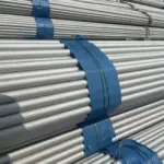
EN 10312 Welded Stainless Steel Tubes
June 22, 2026
1 Scope
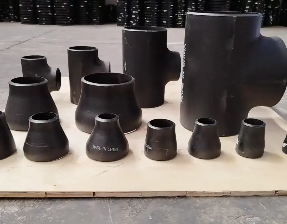
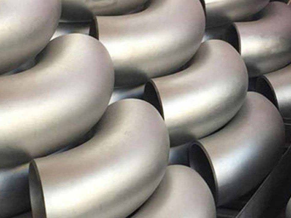
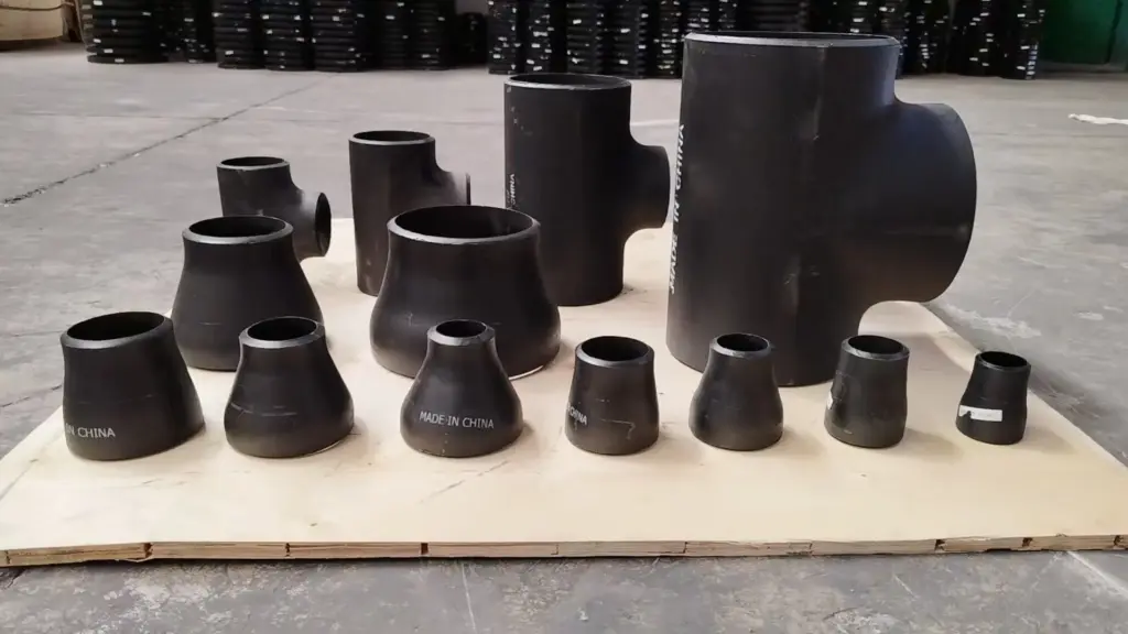
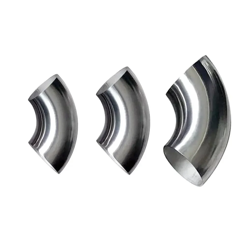
This standard specifies the dimensions, tolerances, technical requirements, inspection and marking of carbon steel, alloy steel and austenitic stainless steel butt-welding seamless pipe fittings (including elbows, reducers, tees, crosses and caps).
This standard applies to carbon steel, alloy steel and austenitic stainless steel butt-welding seamless pipe fittings used for pipeline engineering in petroleum, chemical, hydropower, metallurgy, textile and other industries.
2 Referenced Standards
- GB 8163 Seamless Steel Pipes for Liquid Service
- GB 6479 High-pressure Seamless Steel Pipes for Chemical Fertilizer Equipment
- GB 5310 Seamless Steel Pipes for High-pressure Boilers
- GB 3087 Seamless Steel Pipes for Low and Medium Pressure Boilers
- GB 2270 Stainless Steel Seamless Steel Pipes
- GB 3077 Alloy Structural Steel – Technical Requirements
- GB 3274 Technical Conditions for Hot Rolled Carbon Structural Steel and Low Alloy Structural Steel Thick Plates
- GB 912 Carbon Structural Steel and Low Alloy Structural Steel Thin Steel Plates
- GB 6654 Carbon Steel and Low Alloy Steel Thick Plates for Pressure Vessels
- GB 713 Carbon Steel and Low Alloy Steel Plates for Boiler Manufacturing
- GB 3280 Cold Rolled Stainless Steel Plates
- GB 4237 Hot Rolled Stainless Steel Plates
3 Classification
3.1 Types and Codes
The types and codes of butt-welding seamless pipe fittings specified in this standard are shown in Table 1.
Table 1 Types and Codes of Butt-Welding Seamless Pipe Fittings
| Product | Type | Code |
|---|---|---|
| 45° Elbow | Long Radius | 45E(L) |
| 90° Elbow | Long Radius | 90E(L) |
| Short Radius | 90E(S) | |
| Long Radius Reducing Elbow | Long Radius | 90E(L)R |
| 180° Elbow | Long Radius | 180E(L) |
| Short Radius | 180E(S) | |
| Reducer | Concentric | R(C) |
| Eccentric | R(E) | |
| Tee | Equal Diameter | T(S) |
| Reducing | T(R) | |
| Cross | Equal Diameter | CR(S) |
| Reducing | CR(R) | |
| Pipe Cap | — | C |
3.2 Dimensions and Tolerances
3.2.1 Dimensions
There are two series (Series A and Series B) for the outside diameter of fitting ends. Series A shall be preferred.
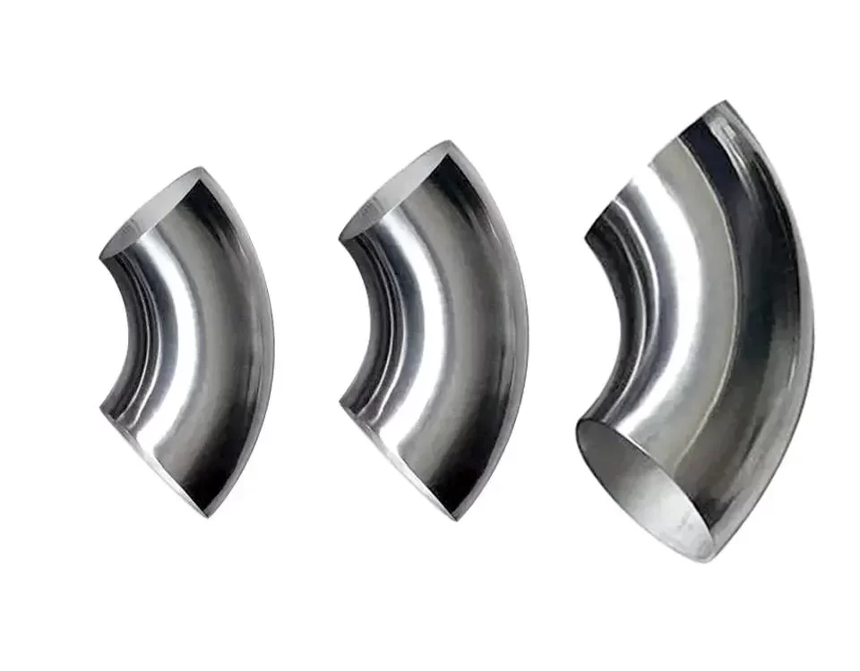
3.2.1.1 Elbows
The structure and dimensions of elbows shall comply with Figure 1 and Table 2 respectively.
Note: Values in parentheses shall be avoided as far as possible.
Table 2 Dimensions of 45° Elbow, 90° Elbow and 180° Elbow (Unit: mm)
| Nominal Diameter DN | End Outside Diameter D | Center to End H 45° Elbow |
Center to End F 90° Elbow |
Center to Center P 180° Elbow |
Back to End K 180° Elbow |
||||
|---|---|---|---|---|---|---|---|---|---|
| Series A | Series B | Long Radius | Long Radius | Short Radius | Long Radius | Short Radius | Long Radius | Short Radius | |
| 15 | 21.3 | 18 | 16 | 38 | — | 76 | — | 48 | — |
| 20 | 26.9 | 25 | 16 | 38 | — | 76 | — | 51 | — |
| 25 | 33.7 | 32 | 16 | 38 | 25 | 76 | 51 | 56 | 41 |
| 32 | 42.4 | 38 | 20 | 48 | 32 | 95 | 64 | 70 | 52 |
| 40 | 48.3 | 45 | 24 | 57 | 38 | 114 | 76 | 83 | 62 |
| 50 | 60.3 | 57 | 32 | 76 | 51 | 152 | 102 | 106 | 81 |
| 65 | 76.1 (73) | 76 | 40 | 95 | 64 | 191 | 127 | 132 | 100 |
| 80 | 88.9 | 89 | 47 | 114 | 76 | 229 | 152 | 159 | 121 |
| 90 | 101.6 | — | 55 | 133 | 89 | 267 | 178 | 184 | 140 |
| 100 | 114.3 | 108 | 63 | 152 | 102 | 305 | 203 | 210 | 159 |
| 125 | 139.7 | 133 | 79 | 190 | 127 | 381 | 254 | 262 | 197 |
| 150 | 168.3 | 159 | 95 | 229 | 152 | 457 | 305 | 313 | 237 |
| 200 | 219.1 | 219 | 126 | 305 | 203 | 610 | 406 | 414 | 313 |
| 250 | 273.0 | 273 | 158 | 381 | 254 | 762 | 508 | 518 | 391 |
| 300 | 323.9 | 325 | 189 | 457 | 305 | 914 | 610 | 619 | 467 |
| 350 | 355.6 | 377 | 221 | 533 | 356 | 1067 | 711 | 711 | 533 |
| 400 | 406.4 | 426 | 253 | 610 | 406 | 1219 | 813 | 813 | 610 |
| 450 | 457.0 | 478 | 284 | 686 | 457 | 1372 | 914 | 914 | 686 |
| 500 | 508.0 | 529 | 316 | 762 | 508 | 1524 | 1016 | 1016 | 762 |
3.2.1.2 90° Long Radius Reducing Elbow
The structure and dimensions of 90° long radius reducing elbow shall comply with Figure 2 and Table 3 respectively.
Table 3 Dimensions of 90° Long Radius Reducing Elbow (Unit: mm)
| Nominal Diameter DN | End Outside Diameter D₁ | End Outside Diameter D₂ | Center to End F | ||
|---|---|---|---|---|---|
| Series A | Series B | Series A | Series B | mm | |
| 50×40 | 60.3 | 57 | 48.3 | 45 | 76 |
| 50×32 | 60.3 | 57 | 42.4 | 38 | 76 |
| 50×25 | 60.3 | 57 | 33.7 | 32 | 76 |
| 65×50 | 76.1 (73) | 76 | 60.3 | 57 | 95 |
| 65×40 | 76.1 (73) | 76 | 48.3 | 45 | 95 |
| 65×32 | 76.1 (73) | 76 | 42.4 | 38 | 95 |
| 80×65 | 88.9 | 89 | 76.1 (73) | 76 | 114 |
| 80×50 | 88.9 | 89 | 60.3 | 57 | 114 |
| 80×40 | 88.9 | 89 | 48.3 | 45 | 114 |
| 90×80 | 101.6 | — | 88.9 | — | 133 |
| 90×65 | 101.6 | — | 76.1 (73) | — | 133 |
| 90×50 | 101.6 | — | 60.3 | — | 133 |
| 100×90 | 114.3 | — | 101.6 | — | 152 |
| 100×80 | 114.3 | 108 | 88.9 | 89 | 152 |
| 100×65 | 114.3 | 108 | 76.1 (73) | 76 | 152 |
| 100×50 | 114.3 | 108 | 60.3 | 57 | 152 |
| 125×100 | 139.7 | 133 | 114.3 | 108 | 190 |
| 125×90 | 139.7 | — | 101.6 | — | 190 |
| 125×80 | 139.7 | 133 | 88.9 | 89 | 190 |
| 125×65 | 139.7 | 133 | 76.1 (73) | 76 | 190 |
| 150×125 | 168.3 | 159 | 139.7 | 133 | 229 |
| 150×100 | 168.3 | 159 | 114.3 | 108 | 229 |
| 150×90 | 168.3 | — | 101.6 | — | 229 |
| 150×80 | 168.3 | 159 | 88.9 | 89 | 229 |
| 200×150 | 219.1 | 219 | 168.3 | 159 | 305 |
| 200×125 | 219.1 | 219 | 139.7 | 133 | 305 |
| 200×100 | 219.1 | 219 | 114.3 | 108 | 305 |
| 250×200 | 273.0 | 273 | 219.1 | 219 | 381 |
| 250×150 | 273.0 | 273 | 168.3 | 159 | 381 |
| 250×125 | 273.0 | 273 | 139.7 | 133 | 381 |
| 300×250 | 323.9 | 325 | 273.0 | 273 | 457 |
| 300×200 | 323.9 | 325 | 219.1 | 219 | 457 |
| 300×150 | 323.9 | 325 | 168.3 | 159 | 457 |
| 350×300 | 355.6 | 377 | 323.9 | 325 | 533 |
| 350×250 | 355.6 | 377 | 273.0 | 273 | 533 |
| 350×200 | 355.6 | 377 | 219.1 | 219 | 533 |
| 400×350 | 406.4 | 426 | 355.6 | 377 | 610 |
| 400×300 | 406.4 | 426 | 323.9 | 325 | 610 |
| 400×250 | 406.4 | 426 | 273.0 | 273 | 610 |
| 450×400 | 457.0 | 478 | 406.4 | 426 | 686 |
| 450×350 | 457.0 | 478 | 355.6 | 377 | 686 |
| 450×300 | 457.0 | 478 | 323.9 | 325 | 686 |
| 450×250 | 457.0 | 478 | 273.0 | 273 | 686 |
| 500×450 | 508.0 | 529 | 457.0 | 478 | 762 |
| 500×400 | 508.0 | 529 | 406.4 | 426 | 762 |
| 500×350 | 508.0 | 529 | 355.6 | 377 | 762 |
| 500×300 | 508.0 | 529 | 323.9 | 325 | 762 |
| 500×250 | 508.0 | 529 | 273.0 | 273 | 762 |
Note: Values in parentheses shall be avoided as far as possible.
3.2.1.3 Reducers
The structure and dimensions of concentric and eccentric reducers shall comply with Figure 3 and Table 4 respectively.
Table 4 Dimensions of Reducers (Unit: mm)
| Nominal Diameter DN | End Outside Diameter D₁ | End Outside Diameter D₂ | Length L | ||
|---|---|---|---|---|---|
| Series A | Series B | Series A | Series B | mm | |
| 20×15 | 26.9 | 25 | 21.3 | 18 | 38 |
| 25×20 | 33.7 | 32 | 26.9 | 25 | 51 |
| 25×15 | 33.7 | 32 | 21.3 | 18 | 51 |
| 32×25 | 42.4 | 38 | 33.7 | 32 | 51 |
| 32×20 | 42.4 | 38 | 26.9 | 25 | 51 |
| 32×15 | 42.4 | 38 | 21.3 | 18 | 51 |
| 40×32 | 48.3 | 45 | 42.4 | 38 | 64 |
| 40×25 | 48.3 | 45 | 33.7 | 32 | 64 |
| 40×20 | 48.3 | 45 | 26.9 | 25 | 64 |
| 40×15 | 48.3 | 45 | 21.3 | 18 | 64 |
| 50×40 | 60.3 | 57 | 48.3 | 45 | 76 |
| 50×32 | 60.3 | 57 | 42.4 | 38 | 76 |
| 50×25 | 60.3 | 57 | 33.7 | 32 | 76 |
| 50×20 | 60.3 | 57 | 26.9 | 25 | 76 |
| 65×50 | 76.1 (73) | 76 | 60.3 | 57 | 89 |
| 65×40 | 76.1 (73) | 76 | 48.3 | 45 | 89 |
| 65×32 | 76.1 (73) | 76 | 42.4 | 38 | 89 |
| 65×25 | 76.1 (73) | 76 | 33.7 | 32 | 89 |
| 80×65 | 88.9 | 89 | 76.1 (73) | 76 | 89 |
| 80×50 | 88.9 | 89 | 60.3 | 57 | 89 |
| 80×40 | 88.9 | 89 | 48.3 | 45 | 89 |
| 80×32 | 88.9 | 89 | 42.4 | 38 | 89 |
| 90×80 | 101.6 | — | 88.9 | — | 102 |
| 90×65 | 101.6 | — | 76.1 (73) | — | 102 |
| 90×50 | 101.6 | — | 60.3 | — | 102 |
| 90×40 | 101.6 | — | 48.3 | — | 102 |
| 90×32 | 101.6 | — | 42.4 | — | 102 |
| 100×90 | 114.3 | — | 101.6 | — | 102 |
| 100×80 | 114.3 | 108 | 88.9 | 89 | 102 |
| 100×65 | 114.3 | 108 | 76.1 (73) | 76 | 102 |
| 100×50 | 114.3 | 108 | 60.3 | 57 | 102 |
| 100×40 | 114.3 | 108 | 48.3 | 45 | 102 |
| 125×100 | 139.7 | 133 | 114.3 | 108 | 127 |
| 125×90 | 139.7 | — | 101.6 | — | 127 |
| 125×80 | 139.7 | 133 | 88.9 | 89 | 127 |
| 125×65 | 139.7 | 133 | 76.1 (73) | 76 | 127 |
| 125×50 | 139.7 | 133 | 60.3 | 57 | 127 |
| 150×125 | 168.3 | 159 | 139.7 | 133 | 140 |
| 150×100 | 168.3 | 159 | 114.3 | 108 | 140 |
| 150×90 | 168.3 | — | 101.6 | — | 140 |
| 150×80 | 168.3 | 159 | 88.9 | 89 | 140 |
| 150×65 | 168.3 | 159 | 76.1 (73) | 76 | 140 |
| 200×150 | 219.1 | 219 | 168.3 | 159 | 152 |
| 200×125 | 219.1 | 219 | 139.7 | 133 | 152 |
| 200×100 | 219.1 | 219 | 114.3 | 108 | 152 |
| 200×90 | 219.1 | — | 101.6 | — | 152 |
| 250×200 | 273.0 | 273 | 219.1 | 219 | 178 |
| 250×150 | 273.0 | 273 | 168.3 | 159 | 178 |
| 250×125 | 273.0 | 273 | 139.7 | 133 | 178 |
| 250×100 | 273.0 | 273 | 114.3 | 108 | 178 |
| 300×250 | 323.9 | 325 | 273.0 | 273 | 203 |
| 300×200 | 323.9 | 325 | 219.1 | 219 | 203 |
| 300×150 | 323.9 | 325 | 168.3 | 159 | 203 |
| 300×125 | 323.9 | 325 | 139.7 | 133 | 203 |
| 350×300 | 355.6 | 377 | 323.9 | 325 | 330 |
| 350×250 | 355.6 | 377 | 273.0 | 273 | 330 |
| 350×200 | 355.6 | 377 | 219.1 | 219 | 330 |
| 350×150 | 355.6 | 377 | 168.3 | 159 | 330 |
| 400×350 | 406.4 | 426 | 355.6 | 377 | 356 |
| 400×300 | 406.4 | 426 | 323.9 | 325 | 356 |
| 400×250 | 406.4 | 426 | 273.0 | 273 | 356 |
| 400×200 | 406.4 | 426 | 219.1 | 219 | 356 |
| 450×400 | 457.2 | 478 | 406.4 | 426 | 381 |
| 450×350 | 457.2 | 478 | 355.6 | 377 | 381 |
| 450×300 | 457.2 | 478 | 323.9 | 325 | 381 |
| 450×250 | 457.2 | 478 | 273.0 | 273 | 381 |
| 500×450 | 508.0 | 529 | 457.0 | 478 | 508 |
| 500×400 | 508.0 | 529 | 406.4 | 426 | 508 |
| 500×350 | 508.0 | 529 | 355.6 | 377 | 508 |
| 500×300 | 508.0 | 529 | 323.9 | 325 | 508 |
Note: Values in parentheses shall be avoided as far as possible.
3.2.1.4 Equal Diameter Tees and Crosses
The structure and dimensions of equal diameter tees and crosses shall comply with Figure 4 and Table 5 respectively.
Table 5 Dimensions of Equal Diameter Tees and Crosses (Unit: mm)
| Nominal Diameter DN | End Outside Diameter D₁, D₂ | Center to End C, M | |
|---|---|---|---|
| Series A | Series B | mm | |
| 15 | 21.3 | 18 | 25 |
| 20 | 26.9 | 25 | 29 |
| 25 | 33.7 | 32 | 38 |
| 32 | 42.4 | 38 | 48 |
| 40 | 48.3 | 45 | 57 |
| 50 | 60.3 | 57 | 64 |
| 65 | 76.1 (73) | 76 | 76 |
| 80 | 88.9 | 89 | 86 |
| 90 | 101.6 | — | 95 |
| 100 | 114.3 | 108 | 105 |
| 125 | 139.7 | 133 | 124 |
| 150 | 168.3 | 159 | 143 |
| 200 | 219.1 | 219 | 178 |
| 250 | 273.0 | 273 | 216 |
| 300 | 323.9 | 325 | 254 |
| 350 | 355.6 | 377 | 279 |
| 400 | 406.4 | 426 | 305 |
| 450 | 457.0 | 478 | 343 |
| 500 | 508.0 | 529 | 381 |
Note: Values in parentheses shall be avoided as far as possible.
3.2.1.5 Reducing Tees and Crosses
The structure and dimensions of reducing tees and crosses shall comply with Figure 5 and Table 6 respectively.
Table 6 Dimensions of Reducing Tees and Crosses (Unit: mm)
| Nominal Diameter DN | End Outside Diameter D₁ | End Outside Diameter D₂ | Center to End C | Center to End M | ||
|---|---|---|---|---|---|---|
| Series A | Series B | Series A | Series B | mm | mm | |
| 20×20×15 | 26.9 | 25 | 21.3 | 18 | 29 | 29 |
| 25×25×20 | 33.7 | 32 | 26.9 | 25 | 38 | 38 |
| 25×25×15 | 33.7 | 32 | 21.3 | 18 | 38 | 38 |
| 32×32×25 | 42.4 | 38 | 33.7 | 32 | 48 | 48 |
| 32×32×20 | 42.4 | 38 | 26.9 | 25 | 48 | 48 |
| 32×32×15 | 42.4 | 38 | 21.3 | 18 | 48 | 48 |
| 40×40×32 | 48.3 | 45 | 42.4 | 38 | 57 | 57 |
| 40×40×25 | 48.3 | 45 | 33.7 | 32 | 57 | 57 |
| 40×40×20 | 48.3 | 45 | 26.9 | 25 | 57 | 57 |
| 40×40×15 | 48.3 | 45 | 21.3 | 18 | 57 | 57 |
| 50×50×40 | 60.3 | 57 | 48.3 | 45 | 64 | 60 |
| 50×50×32 | 60.3 | 57 | 42.4 | 38 | 64 | 57 |
| 50×50×25 | 60.3 | 57 | 33.7 | 32 | 64 | 51 |
| 50×50×20 | 60.3 | 57 | 26.9 | 25 | 64 | 44 |
| 65×65×50 | 76.1 (73) | 76 | 60.3 | 57 | 76 | 70 |
| 65×65×40 | 76.1 (73) | 76 | 48.3 | 45 | 76 | 67 |
| 65×65×32 | 76.1 (73) | 76 | 42.4 | 38 | 76 | 64 |
| 65×65×25 | 76.1 (73) | 76 | 33.7 | 32 | 76 | 57 |
| 80×80×65 | 88.9 | 89 | 76.1 (73) | 76 | 86 | 83 |
| 80×80×50 | 88.9 | 89 | 60.3 | 57 | 86 | 76 |
| 80×80×40 | 88.9 | 89 | 48.3 | 45 | 86 | 73 |
| 80×80×32 | 88.9 | 89 | 42.4 | 38 | 86 | 70 |
| 90×90×80 | 101.6 | — | 88.9 | — | 95 | 92 |
| 90×90×65 | 101.6 | — | 76.1 (73) | — | 95 | 89 |
| 90×90×50 | 101.6 | — | 60.3 | — | 95 | 83 |
| 90×90×40 | 101.6 | — | 48.3 | — | 95 | 79 |
| 100×100×90 | 114.3 | — | 101.6 | — | 105 | 102 |
| 100×100×80 | 114.3 | 108 | 88.9 | 89 | 105 | 98 |
| 100×100×65 | 114.3 | 108 | 76.1 (73) | 76 | 105 | 95 |
| 100×100×50 | 114.3 | 108 | 60.3 | 57 | 105 | 89 |
| 100×100×40 | 114.3 | 108 | 48.3 | 45 | 105 | 86 |
| 125×125×100 | 139.7 | 133 | 114.3 | 108 | 124 | 117 |
| 125×125×90 | 139.7 | — | 101.6 | — | 124 | 114 |
| 125×125×80 | 139.7 | 133 | 88.9 | 89 | 124 | 111 |
| 125×125×65 | 139.7 | 133 | 76.1 (73) | 76 | 124 | 108 |
| 125×125×50 | 139.7 | 133 | 60.3 | 57 | 124 | 105 |
| 150×150×125 | 168.3 | 159 | 139.7 | 133 | 143 | 137 |
| 150×150×100 | 168.3 | 159 | 114.3 | 108 | 143 | 130 |
| 150×150×90 | 168.3 | — | 101.6 | — | 143 | 127 |
| 150×150×80 | 168.3 | 159 | 88.9 | 89 | 143 | 124 |
| 150×150×65 | 168.3 | 159 | 76.1 (73) | 76 | 143 | 121 |
| 200×200×150 | 219.1 | 219 | 168.3 | 159 | 178 | 168 |
| 200×200×125 | 219.1 | 219 | 139.7 | 133 | 178 | 162 |
| 200×200×100 | 219.1 | 219 | 114.3 | 108 | 178 | 156 |
| 200×200×90 | 219.1 | — | 101.6 | — | 178 | 152 |
| 250×250×200 | 273.0 | 273 | 219.1 | 219 | 216 | 208 |
| 250×250×150 | 273.0 | 273 | 168.3 | 159 | 216 | 194 |
| 250×250×125 | 273.0 | 273 | 139.7 | 133 | 216 | 191 |
| 250×250×100 | 273.0 | 273 | 114.3 | 108 | 216 | 184 |
| 300×300×250 | 323.9 | 325 | 273.0 | 273 | 254 | 241 |
| 300×300×200 | 323.9 | 325 | 219.1 | 219 | 254 | 229 |
| 300×300×150 | 323.9 | 325 | 168.3 | 159 | 254 | 219 |
| 300×300×125 | 323.9 | 325 | 139.7 | 133 | 254 | 216 |
| 350×350×300 | 355.6 | 377 | 323.9 | 325 | 279 | 270 |
| 350×350×250 | 355.6 | 377 | 273.0 | 273 | 279 | 257 |
| 350×350×200 | 355.6 | 377 | 219.1 | 219 | 279 | 248 |
| 350×350×150 | 355.6 | 377 | 168.3 | 159 | 279 | 238 |
| 400×400×350 | 406.4 | 426 | 355.6 | 377 | 305 | 305 |
| 400×400×300 | 406.4 | 426 | 323.9 | 325 | 305 | 295 |
| 400×400×250 | 406.4 | 426 | 273.0 | 273 | 305 | 283 |
| 400×400×200 | 406.4 | 426 | 219.1 | 219 | 305 | 273 |
| 400×400×150 | 406.4 | 426 | 168.3 | 159 | 305 | 264 |
| 450×450×400 | 457.2 | 478 | 406.4 | 426 | 343 | 330 |
| 450×450×350 | 457.2 | 478 | 355.6 | 377 | 343 | 330 |
| 450×450×300 | 457.2 | 478 | 323.9 | 325 | 343 | 321 |
| 450×450×250 | 457.2 | 478 | 273.0 | 273 | 343 | 308 |
| 450×450×200 | 457.2 | 478 | 219.1 | 219 | 343 | 298 |
| 500×500×450 | 508.0 | 529 | 457.2 | 478 | 381 | 368 |
| 500×500×400 | 508.0 | 529 | 406.4 | 426 | 381 | 356 |
| 500×500×350 | 508.0 | 529 | 355.6 | 377 | 381 | 356 |
| 500×500×300 | 508.0 | 529 | 323.9 | 325 | 381 | 346 |
| 500×500×250 | 508.0 | 529 | 273.0 | 273 | 381 | 333 |
| 500×500×200 | 508.0 | 529 | 219.1 | 219 | 381 | 324 |
Note: Values in parentheses shall be avoided as far as possible.
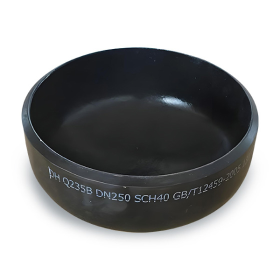
3.2.1.6 Pipe Caps
The structure and dimensions of pipe caps shall comply with Figure 6 and Table 7 respectively.
Notes:
1. Values in parentheses shall be avoided as far as possible.
2. The head of the pipe cap is elliptical, and the length of the semicircular part shall not be less than 1/4 of the inner diameter of the pipe cap.
3. If the nominal wall thickness of the pipe cap is less than or equal to the limiting thickness, adopt dimension E; if it is greater than the limiting thickness, adopt dimension E₁.
Table 7 Dimensions of Pipe Caps (Unit: mm)
| Nominal Diameter DN | End Outside Diameter D | Back to End E | Back to End E₁ | Limiting Thickness for E | |
|---|---|---|---|---|---|
| Series A | Series B | mm | mm | mm | |
| 15 | 21.3 | 18 | 25 | — | — |
| 20 | 26.9 | 25 | 25 | — | — |
| 25 | 33.7 | 32 | 38 | — | — |
| 32 | 42.4 | 38 | 38 | — | — |
| 40 | 48.3 | 45 | 38 | — | — |
| 50 | 60.3 | 57 | 38 | 44 | 5.5 |
| 65 | 76.1 (73) | 76 | 38 | 51 | 7.0 |
| 80 | 88.9 | 89 | 51 | 64 | 7.6 |
| 90 | 101.6 | — | 64 | 76 | 8.1 |
| 100 | 114.3 | 108 | 64 | 76 | 8.6 |
| 125 | 139.7 | 133 | 76 | 89 | 9.5 |
| 150 | 168.3 | 159 | 89 | 102 | 11.0 |
| 200 | 219.1 | 219 | 102 | 127 | 12.7 |
| 250 | 273.0 | 273 | 127 | 152 | 12.7 |
| 300 | 323.9 | 325 | 152 | 178 | 12.7 |
| 350 | 355.6 | 377 | 165 | 191 | 12.7 |
| 400 | 406.4 | 426 | 178 | 203 | 12.7 |
| 450 | 457.0 | 478 | 203 | 229 | 12.7 |
| 500 | 508.0 | 529 | 229 | 254 | 12.7 |
3.2.2 Dimensional Tolerances
3.2.2.1 Limit Deviations of Fitting Dimensions
Notes:
1. Unless otherwise specified by the user, priority shall be given to ensuring the limit deviations of end outside diameter and nominal wall thickness.
2. Wall thickness deviation refers to the limit deviation of nominal wall thickness specified in Appendix A.
Table 8 Limit Deviations of Fitting Dimensions (Unit: mm)
| Item | Fitting Type | Nominal Diameter Range | ||||
|---|---|---|---|---|---|---|
| 15~65 | 80~100 | 125~200 | 250~450 | 500 | ||
| End Outside Diameter | All fittings | +1.6 / -0.8 | ±1.6 | +2.4 / -1.6 | +4.0 / -3.2 | +6.4 / -4.8 |
| End Inside Diameter | — | ±0.8 | ±1.6 | ±3.2 | ±4.8 | — |
| Wall Thickness | All fittings | Not less than 87.5% of the nominal wall thickness | ||||
| Center to End (H, F) | 45° Elbow, 90° Elbow | ±2 | ±3 | |||
| Center to Center (P) | 180° Elbow | ±7 | ±10 | |||
| Back to End (K) | 180° Elbow | ±7 | ±10 | |||
| Total Length (L) | Reducer | ±2 | ±3 | |||
| Center to End (C, M) | Tee, Cross | ±2 | ±3 | |||
| Back to End (E, E₁) | Pipe Cap | ±4 | ±7 | |||
3.2.2.2 Geometric Tolerances of Fittings
The geometric tolerances of fittings shall comply with Figure 7 and Table 9.
Table 9 Geometric Tolerances of Fittings (Unit: mm)
| Item | Fitting Type | Nominal Diameter Range | ||||
|---|---|---|---|---|---|---|
| 15~100 | 125~200 | 250~300 | 350~400 | 450~500 | ||
| X | Elbow, Reducer, Tee, Cross | 1 | 2 | 3 | 4 | 4 |
| Y | Elbow, Tee, Cross | 2 | 4 | 5 | 7 | 10 |
| U | 180° Elbow | 1 | 2 | 2 | 2 | 2 |
3.3 Weld End Groove
The structure and dimensions of weld end groove shall comply with Figure 8.
Notes:
1. For carbon steel and alloy steel fittings with nominal wall thickness less than 4.8 mm, and austenitic stainless steel fittings with nominal wall thickness less than 3.2 mm, the weld end can be processed into a slight bevel or straight end as selected by the manufacturer.
2. Other groove forms are allowed for special requirements, which shall be specified in the contract.
3.4 Marking Examples
1. 90° short radius elbow, DN100, Series A, Wall Class Sch40:
90E(S) 100 – Sch40 GB 12459
2. Concentric reducer, DN100×80, Series B, Wall Class Sch80:
R(C) 100 x80 B – Sch80 GB 12459
3. Reducing tee, DN100×100×80, Series A, Wall Class Sch40:
T(R)100x100x80- Sch40 GB 12459
4 Technical Requirements
4.1 Materials
4.1.1
Except for pipe caps which are made of steel plates, raw materials for butt-welding seamless fittings are all seamless steel pipes. The common material grades and corresponding standards are shown in Table 10. Fittings made of other materials outside Table 10 are allowed upon user’s request.
Table 10 Material Grades and Relevant Standards
| Steel Pipe | Steel Plate | ||
|---|---|---|---|
| Material Grade | Standard No. | Material Grade | Standard No. |
| 10, 20, 16Mn | GB 3087, GB 8163, GB 6479 | A3 | GB 3274, GB 912 |
| 12CrMo, 15CrMo, 1Cr5Mo | GB 6479 | 20R, 16MnR | GB 6654 |
| 12Cr1MoV | GB 5310, GB 8163, GB 3077 | 20g | GB 713 |
| 0Cr19Ni9, 1Cr18Ni9, 1Cr18Ni9Ti | GB 2270 | 12CrMo, 15CrMo, 12Cr1MoV | GB 3077 |
| — | — | 0Cr19Ni9, 1Cr18Ni9, 1Cr18Ni9Ti | GB 3280, GB 4237 |
4.1.2
All materials for seamless fittings shall be accompanied by material certificates, and shall be fully re-inspected in accordance with relevant standards before use.
4.1.3
Additional inspection items such as ultrasonic testing, radiographic testing and magnetic particle inspection can be added upon agreement between the supplier and the purchaser, and shall be specified in the contract.
4.2 Heat Treatment
Fittings after forming shall be heat treated in accordance with Table 11.
Table 11 Heat Treatment Requirements
| Material Grade | Cold Forming | Hot Forming |
|---|---|---|
| A3, 20R, 10, 20, 20g, 16Mn, 16MnR | Normalizing or Annealing | |
| 12CrMo, 15CrMo, 1Cr5Mo, 12Cr1MoV | Quenching and Tempering | |
| 0Cr19Ni9, 1Cr18Ni9, 1Cr18Ni9Ti | Solution Treatment | |
Mechanical properties and other requirements after heat treatment shall comply with relevant standards.
4.3 Surface Treatment
4.3.1
Carbon steel and alloy steel fittings shall be derusted and coated with anti-rust paint on inner and outer surfaces.
4.3.2
Austenitic stainless steel fittings shall be pickled and passivated.
5 Tests
5.1 Hydrostatic Test
All fittings manufactured and inspected in accordance with this standard are not required to conduct hydrostatic test in principle, but they shall withstand the hydrostatic test of the whole system.
5.2 Burst Test
The test medium for burst test is liquid. The burst pressure shall not be less than the calculated value of the connected straight pipe.
Where:
p — Calculated burst pressure of straight pipe, MPa
σ — Minimum tensile strength of pipe material, MPa
S — Nominal wall thickness of pipe, mm
D — Outside diameter of pipe, mm
6 Inspection
6.1 Inspection Items
6.1.1 Surface Quality
Finished fittings shall be free from cracks, overheating scars and other defects affecting strength and appearance. Inner and outer surfaces shall be smooth without oxide scale.
6.1.2 Overall Dimensions
Overall dimensions and tolerances of fittings shall comply with Clause 3.2 of this standard.
6.1.3 Non-destructive Testing
Carbon steel and alloy steel fittings shall be inspected by ultrasonic testing or magnetic particle inspection. Austenitic stainless steel fittings shall be inspected by penetrant testing.
6.1.4 Other Inspections
Additional items including chemical composition, mechanical properties, hydrostatic test and radiographic testing can be added via negotiation and specified in the contract.
6.2 Sampling Rules
Sampling shall be implemented in accordance with relevant standards or agreed by both parties. Each batch of finished fittings shall be delivered with product quality certificate.
7 Marking and Stamping
7.1
Permanent marks shall be sprayed or stamped on obvious positions of finished fittings with clear writing. Marking contents include:
a. Product code;
b. Nominal diameter (including outer diameter series);
c. Wall thickness class or wall thickness value;
d. Standard No.;
e. Material grade;
f. Manufacturer name or trademark.
Example 1: 90° short radius elbow, DN100, Series A, Sch40, material 15CrMo
90E(S) -100- Sch40 -15CrMo GB 12459
Example 2: Concentric reducer, DN100×80, Series B, Sch80, material 16Mn
R(C)-100x80B-Sch80-16Mn GB 12459
7.2
For small-size fittings which cannot mark all contents, items can be omitted in order, or nameplates/labels can be used instead.
7.3
When using steel stamping, the indentation depth shall be controlled to avoid cracks or wall thickness below the specified minimum value.
8 Packaging
8.1
Fitting ends shall be protected. Fittings of different materials shall be packed separately as required by the contract.
8.2
Durable paint shall be used to mark consignee, product name, specification, quantity, net weight, gross weight, manufacturer and delivery information on the outer package.
8.3
Packing list and quality certificate sealed in plastic bags shall be placed inside the package. Finished products shall be stored indoors in dry environment, not exposed outdoors.
8.4 Content of Quality Certificate
a. Manufacturer name and production date;
b. Product name and specification;
c. Chemical composition and mechanical property test results of steel;
d. Results of all inspections.
The certificate shall be sealed and signed by inspectors with inspection date.
8.5 Content of Packing List
a. Manufacturer name;
b. Factory No. and date;
c. Product name, specification, quantity and net weight;
d. Consignee and contract No.;
e. Name and quantity of attached documents.
The packing list shall be sealed and signed by packers with packing date.
Appendix A (Informative) Wall Thickness Classification of Steel Seamless Fittings
Table A1 Wall Thickness Classification (Unit: mm)
</>
| Nominal Diameter DN | Outside Diameter | Nominal Wall Thickness | |||||||||||||
|---|---|---|---|---|---|---|---|---|---|---|---|---|---|---|---|
| Series A | Series B | Sch5s | Sch10s | Sch20s | Sch20 | Sch30 | Sch40 | Sch60 | Sch80 | Sch100 | Sch120 | Sch140 | Sch160 | ||
| 15 | 21.3 | 18 | 1.6 | 2.1 | 2.6 | — | — | 2.9 | — | 3.6 | — | — | — | 4.5 | |
| 20 | 26.9 | 25 | 1.6 | 2.1 | 2.6 | — | — | 2.9 | — | 4.0 | — | — | — | 5.6 | |
| 25 | 33.7 | 32 | 1.6 | 2.8 | 3.2 | — | — | 3.2 | — | 4.5 | — | — | — | 6.3 | |
| 32 | 42.4 | 38 | 1.6 | 2.8 | 3.2 | — | — | 3.6 | — | 5.0 | — | — | — | 6.3 | |
| 40 | 48.3 | 45 | 1.6 | 2.8 | 3.2 | — | — | 3.6 | — | 5.0 | — | — | — | 7.1 | |
| 50 | 60.3 | 57 | 1.6 | 2.8 | 3.6 | 3.2 | — | 4.0 | — | 5.6 | — | — | — | 8.8 | |
| 65 | 76.1(73) | 76 | 2.0 | 3.0 | 3.6 | 4.5 | — | 5.0 | — | 7.1 | — | — | — | 10.0 | |
| 80 | 88.9 | 89 | 2.0 | 3.0 | 4.0 | 4.5 | — | 5.6 | — | 8.0 | — | — | — | 11.0 | |
| 90 | 101.6 | — | 2.0 | 3.0 | 4.0 | 4.5 | — | 5.6 | — | 8.0 | — | — | — | 12.5 | |
| 100 | 114.3 | 108 | 2.0 | 3.0 | 4.0 | 5.0 | — | 5.9 | — | 8.8 | 11.0 | — | — | 14.2 | |
| 125 | 139.7 | 133 | 2.9 | 3.4 | 5.0 | 5.0 | — | 6.3 | — | 10.0 | 12.5 | — | — | 16.0 | |
| 150 | 168.3 | 159 | 2.9 | 3.4 | 5.0 | 5.6 | — | 7.1 | — | 11.0 | 14.2 | — | — | 17.5 | |
| 200 | 219.1 | 219 | 2.9 | 4.0 | 6.3 | 6.3 | 7.1 | 8.0 | 10.0 | 12.5 | 16.0 | 17.5 | 20.0 | 22.2 | |
| 250 | 273.0 | 273 | 3.6 | 4.0 | 6.3 | 6.3 | 8.0 | 8.8 | 12.5 | 16.0 | 17.5 | 22.2 | 25.0 | 28.0 | |
| 300 | 323.9 | 325 | 4.0 | 4.5 | 6.3 | 6.3 | 8.8 | 10.0 | 14.2 | 17.5 | 22.2 | 25.0 | 28.0 | 32.0 | |
| 350 | 355.6 | 377 | 4.0 | 5.0 | — | 8.0 | 10.0 | 11.0 | 16.0 | 20.0 | 25.8 | 28.0 | 32.0 | 36.0 | |
| 400 | 406.4 | 426 | 4.0 | 5.0 | — | 8.0 | 10.0 | 12.5 | 17.5 | 22.2 | 28.0 | 30.0 | 36.0 | 40.0 | |
| 450 | 457.0 | 478 | 4.0 | 5.0 | — | 8.0 | 11.0 | 14.2 | 20.0 | 25.0 | 30.0 | 36.0 | 40.0 | 45.0 | |
| 500 | 508.0 | 529 | 5.0 | 5.6 | — | 10.0 | 12.5 | 16.0 | 20.0 | 28.0 | 32.0 | 40.0 | 45.0 | 50.0 | |
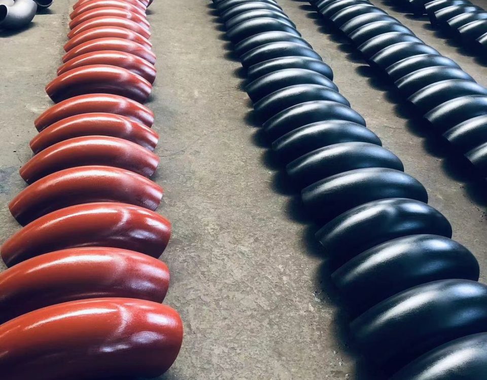
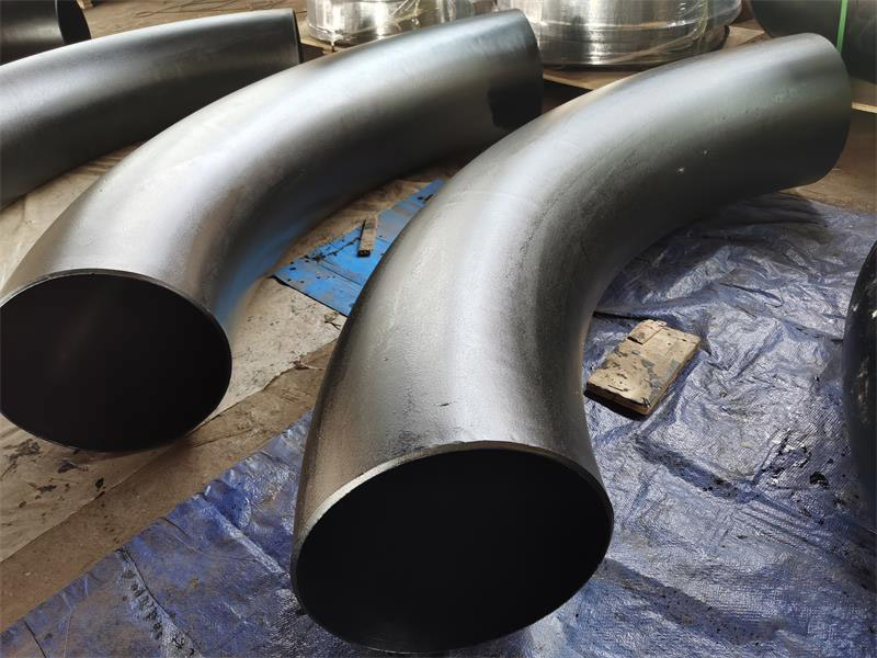
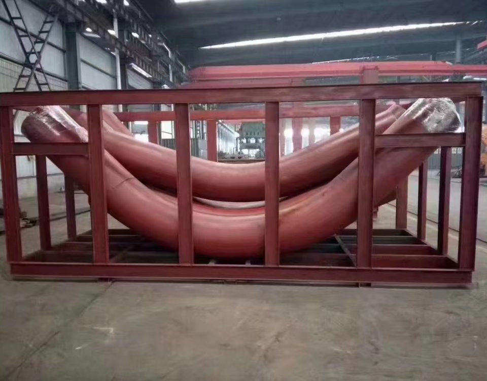
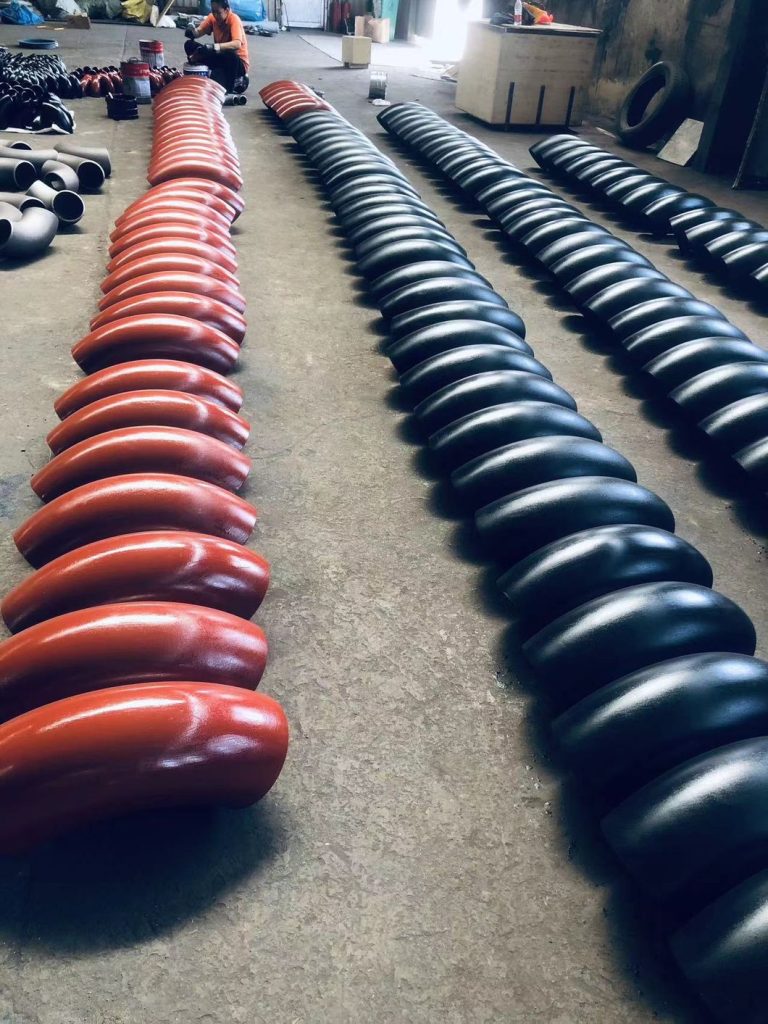
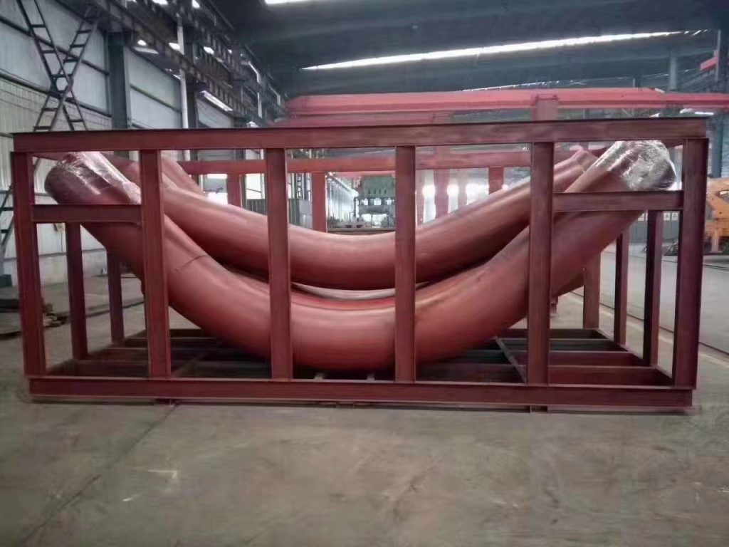
Induction bends come in standard bend angles (e.g. 45°, 90°, etc.) or can be custom made to specific bend angles. Compound bends (out-of-plane) bends in a single joint of pipe can also be produced. The bend radius is specified as a function of the diameter. For example, common bend radii for induction bends are 3D, 5D and 7D, where D is the nominal pipe diameter.
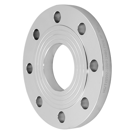
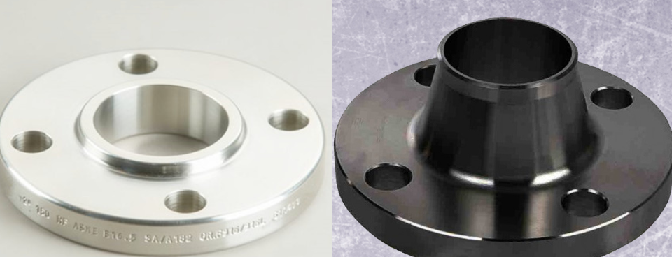
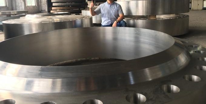
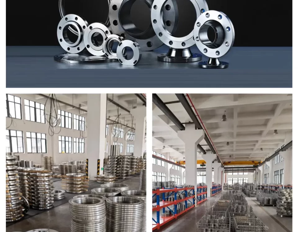
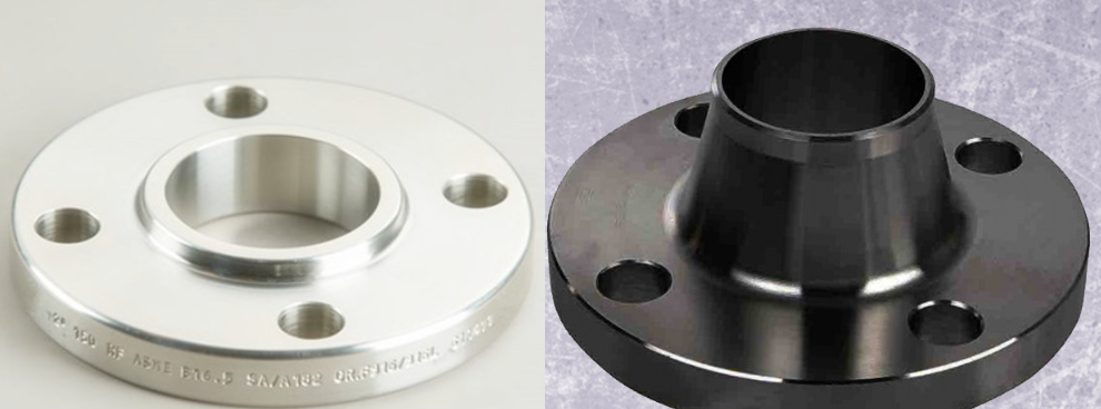
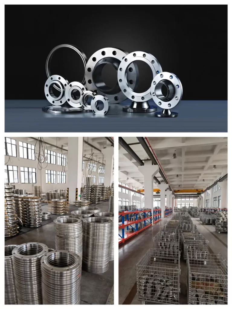
Duplex 2205 and Super Duplex 2507 stainless steel flanges are characterized by their high yield strength, which is twice that of the annealed yield strength of typical austenitic stainless steels, like 304 and 316 stainless steel flanges. Because of this, Duplex 2205 and Super Duplex 2507 steel are some of the most common grades of duplex used for flanges with Super Duplex 2507 flanges being the more corrosion resistant grade of the two.