
Hot Dipped Galvanized ERW Steel Pipe
April 6, 2026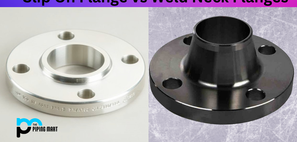
Weld Neck Flange (WNRF): The Ultimate Technical Specification Guide
Comprehensive analysis of Weld Neck Flanges, including Dimension Tables, Material Grades (ASTM A105/A182), Sealing Principles, and Global Manufacturing Standards (ASME/HG/GB).
1. Understanding Weld Neck Flanges (WNRF)
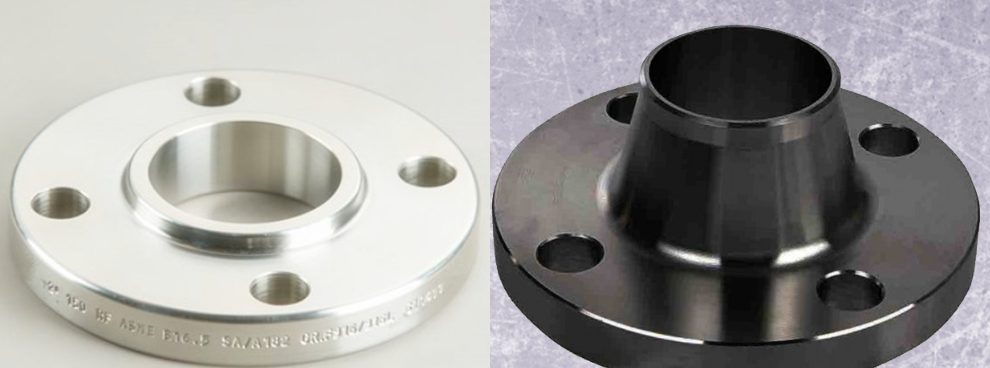
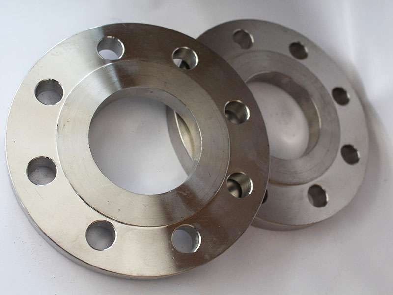
A Weld Neck Flange (WNRF), also known as a high-hub flange or tapered hub flange, is a type of flange designed to be joined to a piping system by butt welding. Unlike the Slip-On Flange, which is connected via fillet welds, the WNRF features a prominent neck that is bored to match the inside diameter (ID) of the matching pipe. This structure ensures there is no restriction in flow and significantly reduces turbulence and erosion at the joint.
Weld Neck Flanges are the preferred choice for high-pressure, high-temperature, and severe stress applications. The tapered hub provides a smooth transition of stress from the flange to the pipe, making it highly resistant to dishing and mechanical vibration.
Key Functional Advantages:
- Superior Rigidity: Ideal for systems with pressure fluctuations.
- Stress Distribution: High-hub design minimizes stress concentration.
- Zero Flow Obstruction: Matching bore eliminates turbulence.
- Leak Integrity: Exceptional performance in hazardous media transport.
2. Technical Parameters & Structural Dimensions
The manufacturing of WNRF flanges requires extreme precision in CNC machining to ensure alignment with international piping schedules. Below are the core dimensional metrics for standard production runs (DN10 to DN2000).
Table 1: General WNRF Dimensional Range
| Parameter Category | Metric Range (Metric/Imperial) |
|---|---|
| Flange Outer Diameter (OD) | 75mm – 2190mm |
| Bolt Circle Diameter (BCD) | 50mm – 2130mm |
| Bolt Hole Diameter | 11mm – 30mm |
| Number of Bolt Holes | 4 – 48 Holes |
| Thread/Bolt Size | M10 – M27 (Equivalent to 1/2″ – 2-1/2″) |
| Flange Thickness | 12mm – 58mm |
| Pipe OD Compatibility | 17.2mm – 2032mm |
| Flange Inside Diameter (ID) | 15mm – 2024mm |
| Theoretical Weight | 0.36kg – 234.6kg (Up to DN1800) |
3. Comprehensive Material Selection & Global Grades
Material integrity is the cornerstone of WNRF safety. We provide full traceability for Carbon Steel, Stainless Steel, and Alloy Steel grades compliant with ASTM and EN standards.
A. Carbon Steel (Most Common)
Standard for non-corrosive, high-pressure utility lines.
- ASTM A105: Standard forged carbon steel.
- 20#, Q235, 16Mn: GB standard equivalents.
- ASTM A350 LF1/LF2/LF3: Low-temperature service.
- ASTM A694: F42, F52, F60, F70 (High yield).
B. Stainless & Alloy Steel Matrix
| Category | Commonly Used Grades |
|---|---|
| Stainless Steel | ASTM A182 F304, F304L, F316, F316L, 321, 1Cr18Ni9Ti |
| Alloy Steel | ASTM A182 F1, F5, F9, F11, F12, F22, F91, 12Cr1MoV, 15CrMo |
| Special Alloy | A335 P22, St45.8/III, 12Cr2Mo1 |
4. International Reference Standards & Ratings
Our WNRF products are manufactured in strict accordance with chemical, mechanical, and marine standards to ensure global interoperability.
Chemical & Industrial Standards
- HG/T Standards: HG20593-2009, HG20615-2009
- GB National Standards: GB/T9119-2010, GB/T2555-81
- JB Machinery Standards: JB/T81-94, JB/T74-94
- Marine Standards: CB M1001-81
Pressure Class Coverage
Available in a wide range of Nominal Pressure (PN) ratings:
PN0.6MPa
PN1.0MPa
PN1.6MPa
PN2.5MPa
PN4.0MPa
5. Sealing Principles & Performance Mechanics
The sealing mechanism of a Weld Neck Flange involves the compression of a gasket between two matching flange faces. However, the First Principle of flange sealing highlights a critical engineering challenge: the “Bolt Load Paradox.”
“Essentially, a traditional flange is an inefficient seal. Approximately 50% of the bolt load is consumed by simply compressing the gasket, leaving only 50% of the load to resist the internal system pressure.”
Gasket Material Compatibility Matrix
Selection of the correct gasket determines the longevity of the WNRF joint under thermal expansion and cycling loads.
| Gasket Type | Temperature Limit | Pressure Limit | Best For |
|---|---|---|---|
| Rubber Gasket | < 120°C | Low | Water/Utility lines |
| Asbestos Rubber | < 450°C (Steam) | < 5.0 MPa | Oil and general chemicals |
| Spiral Wound | High Range | High | Steam, thermal oil, variable loads |
| Metal Lens Gasket | High/Cryo | Extreme | High-pressure vessels (Copper/SS) |
6. Precision Forging & CNC Production Chain
To ensure zero-leakage integrity, our WNRF manufacturing process adheres to strict metallurgical controls.
Forging: Pure material or billet forging for structural density.
Cutting: Oxygen furnace billet cutting or precision pressing.
CNC Machining: High-precision CNC lathe turning for face finish.
Drilling: CNC radial arm drilling for bolt hole alignment.
7. Final Quality Inspection & Logistics
Our WNRF products are finished to a high aesthetic and functional standard: smooth surfaces, anti-corrosive coating, and shock-proof packaging.
| Surface Treatment | Anti-rust oil, Black paint, Yellow varnish, or Cold/Hot-dip Galvanizing. |
| Inspection Criteria | Dimensional check, Ultrasonic testing (UT), and Magnetic Particle Inspection (MPI). |
| Export Packaging | Fumigation-free wooden cases, pallets, and moisture-proof plastic film wrapping. |
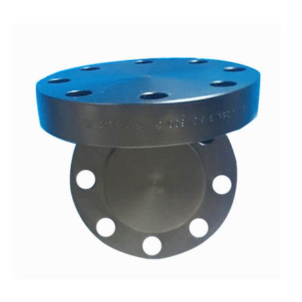
Weld Neck Flange (WNRF) Technical Profile
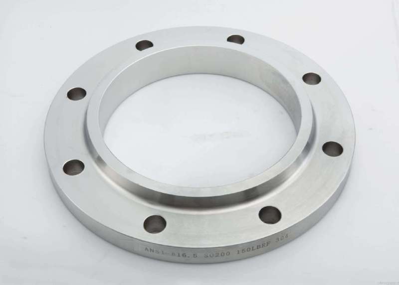
The Weld Neck Flange is a high-integrity component designed for transition into a piping system via butt welding. Distinguished by its long, tapered hub, this flange is engineered to transfer stresses to the pipeline, effectively reducing high stress concentrations at the base of the flange.
While WNRF flanges command a higher price point due to complex forging requirements and labor-intensive alignment, they are the industry standard for high-pressure, high-temperature, and sub-zero (cryogenic) applications. The internal bore is machined to match the pipe’s internal diameter, ensuring a smooth flow profile with minimal turbulence and erosion.
8. More Material Specifications & Grade Matrix
We offer a diverse metallurgical range to meet specific corrosion and mechanical requirements.
| Category | Common Grades & Standards |
|---|---|
| Stainless Steel | ASTM A182/A240 F304, 304L, 316, 316L, 316Ti, 310S, 321, 347, 904L |
| Carbon Steel | ASTM A105, A350 LF2/LF3, A181 LF2, A516 Gr.70, A36, A694 F42-F70 |
| Duplex & Super Duplex | ASTM A182 F44, F51, F53, F55, F60 (S31803/S32205) |
| Alloy Steel | ASTM A182 & A387 F1, F5, F9, F11, F12, F22, F91 |
| Nickel Alloys | Monel 400/500, Inconel 600/625/800/825, Hastelloy C276, Alloy 20 |
| Copper Alloy (Cu-Ni) | ASTM SB61/SB62, UNS C70600 (90/10), C71500 (70/30) |
9. ASME B16.5 Class 150 Weld Neck Flange Dimensions
The following parameters define the Raised Face (RF) WNRF geometry. All measurements are in millimeters (mm) unless specified.
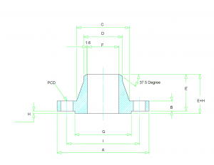
| Size (Inch) | Size (mm) | OD (A) | Thick (B) | Hub OD (C) | Neck OD (D) | Length (E) | RF Dia (G) | PCD (I) | RF Ht (H) |
|---|---|---|---|---|---|---|---|---|---|
| 1/2″ | 15 | 90 | 9.6 | 30 | 21.3 | 46 | 34.9 | 60.3 | 1.6 |
| 3/4″ | 20 | 100 | 11.2 | 38 | 26.7 | 51 | 42.9 | 69.9 | 1.6 |
| 1″ | 25 | 110 | 12.7 | 49 | 33.4 | 54 | 50.8 | 79.4 | 1.6 |
| 1 1/4″ | 32 | 115 | 14.3 | 59 | 42.2 | 56 | 63.5 | 88.9 | 1.6 |
| 1 1/2″ | 40 | 125 | 15.9 | 65 | 48.3 | 60 | 73.0 | 98.4 | 1.6 |
| 2″ | 50 | 150 | 17.5 | 78 | 60.3 | 62 | 92.1 | 120.7 | 1.6 |
| 3″ | 80 | 190 | 22.3 | 108 | 88.9 | 68 | 127.0 | 152.4 | 1.6 |
| 4″ | 100 | 230 | 22.3 | 135 | 114.3 | 75 | 157.2 | 190.5 | 1.6 |
| 6″ | 150 | 280 | 23.9 | 192 | 168.3 | 87 | 215.9 | 241.3 | 1.6 |
| 8″ | 200 | 345 | 27.0 | 246 | 219.1 | 100 | 269.9 | 298.5 | 1.6 |
| 12″ | 300 | 485 | 30.2 | 365 | 323.8 | 113 | 381.0 | 431.8 | 1.6 |
| 16″ | 400 | 595 | 35.0 | 457 | 406.4 | 125 | 469.9 | 539.8 | 1.6 |
| 20″ | 500 | 700 | 41.3 | 559 | 508.0 | 143 | 584.2 | 635.0 | 1.6 |
| 24″ | 600 | 815 | 46.1 | 663 | 610.0 | 151 | 692.2 | 749.3 | 1.6 |
*Note: The Welding Neck Bore (F) must be specified by the customer as it is derived from the matching pipe schedule (e.g., Sch 40, Sch 80, Sch XS).
10. Industrial Applications & Sector Deployment
WNRF flanges are engineered for performance in volatile environments. Key sectors include:
Energy & Resource Transport
- Oil and Gas Trunk Pipelines
- Power Plant Steam Generation
- Offshore Platform Piping
Process Engineering
- Chemical & Petrochemical Processing
- Paper & Pulp Slurry Transport
- Food & Pharmaceutical Grade Systems
Available Facing Types: Raised Face (RF), Flat Face (FF), Ring Type Joint (RTJ), Tongue & Groove (T&G), and Male & Female (M&F).
Request a Technical Quote for WNRF Flanges
From DN10 to DN2000, in Carbon, Stainless, or Alloy Steel. Ensure your piping system’s integrity with world-class Weld Neck Flanges.
Keywords: Weld Neck Flange, WNRF Flange Dimensions, ASTM A105 Flange, Stainless Steel WN Flange, PN1.6MPa Flange Weight, ASME B16.5 Flange Standard.
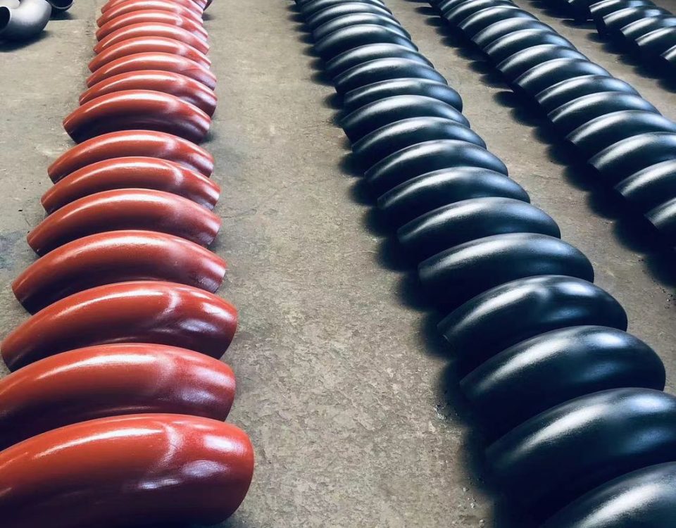
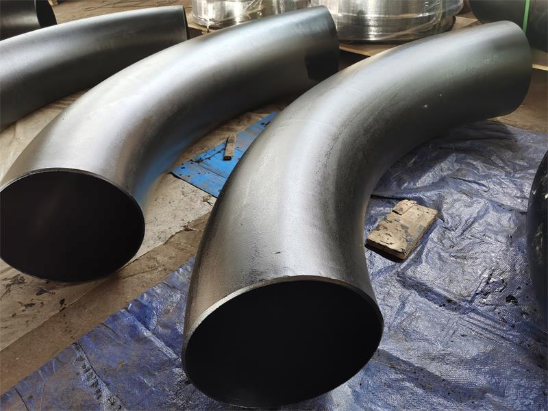
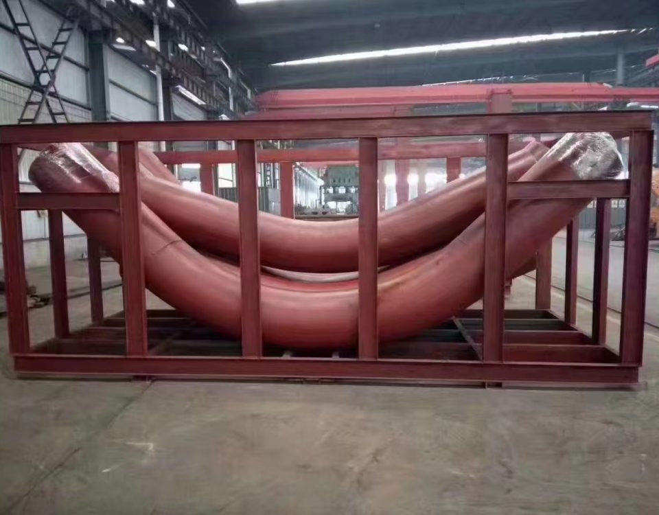
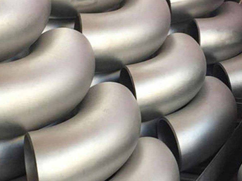
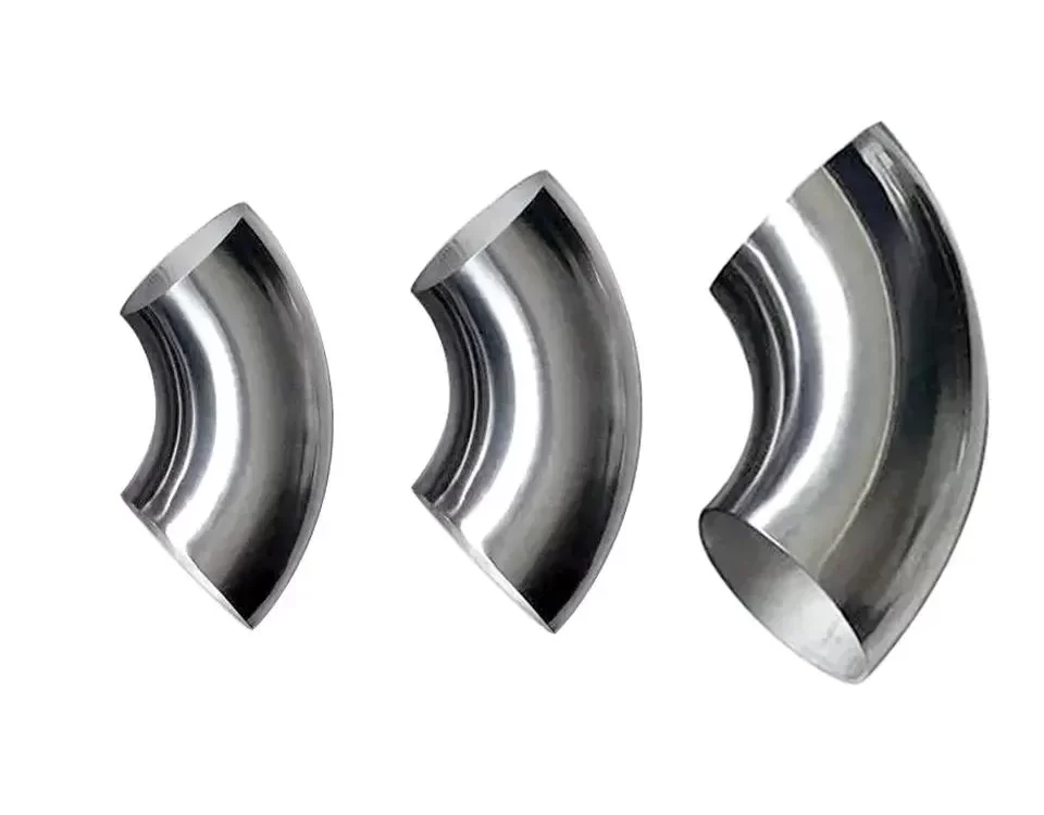
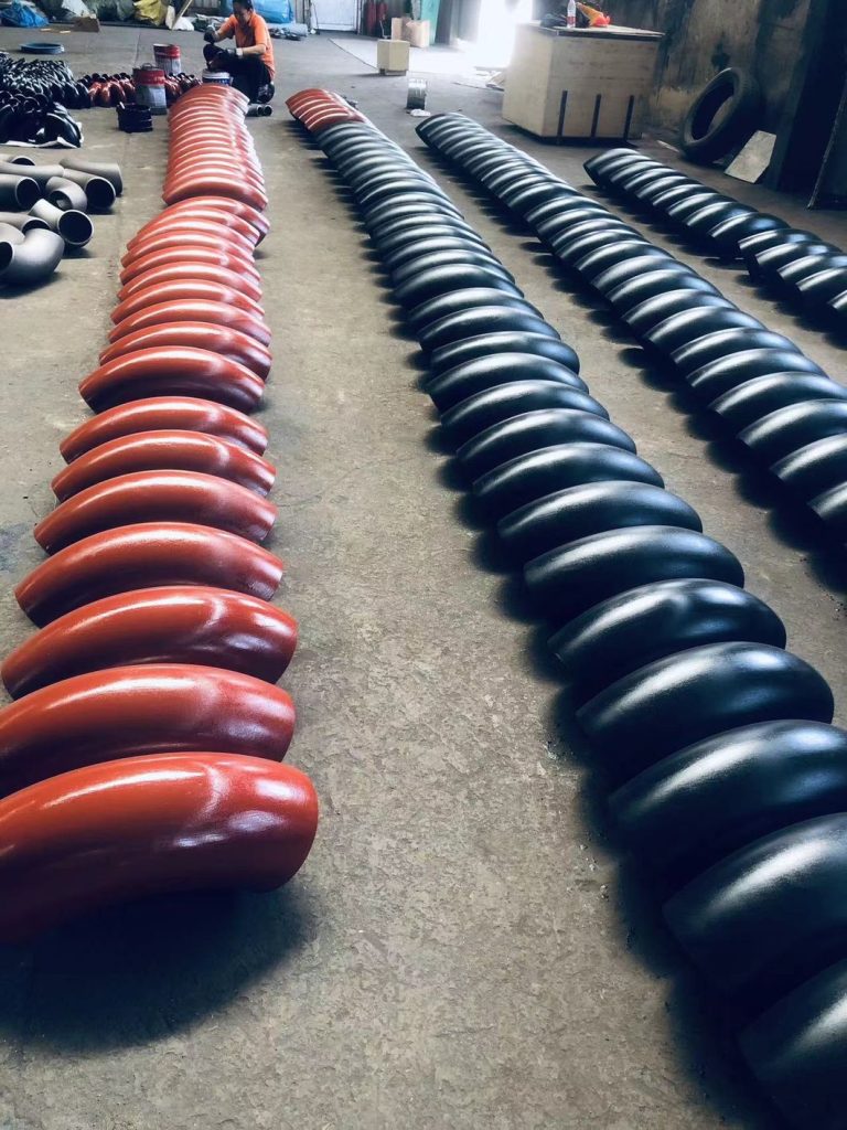
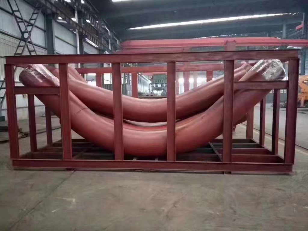
Induction bends come in standard bend angles (e.g. 45°, 90°, etc.) or can be custom made to specific bend angles. Compound bends (out-of-plane) bends in a single joint of pipe can also be produced. The bend radius is specified as a function of the diameter. For example, common bend radii for induction bends are 3D, 5D and 7D, where D is the nominal pipe diameter.
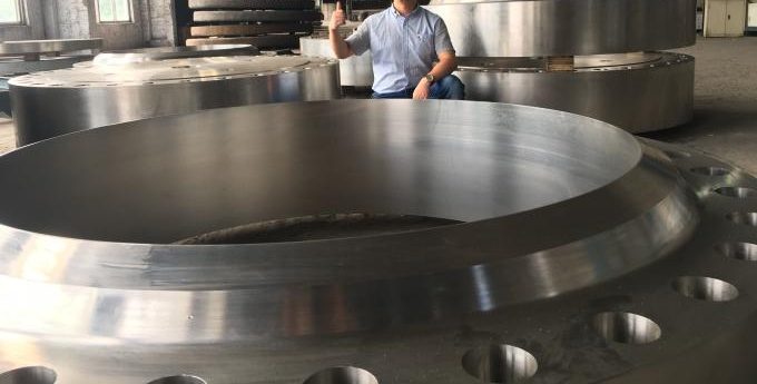
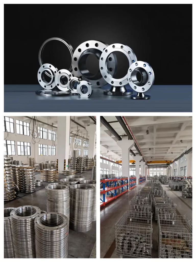
Duplex 2205 and Super Duplex 2507 stainless steel flanges are characterized by their high yield strength, which is twice that of the annealed yield strength of typical austenitic stainless steels, like 304 and 316 stainless steel flanges. Because of this, Duplex 2205 and Super Duplex 2507 steel are some of the most common grades of duplex used for flanges with Super Duplex 2507 flanges being the more corrosion resistant grade of the two.