

UL 852 Fire Sprinkler Pipe
May 17, 2026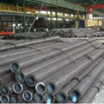
JIS G 4105 SCM420 Seamless Steel Pipe
May 30, 2026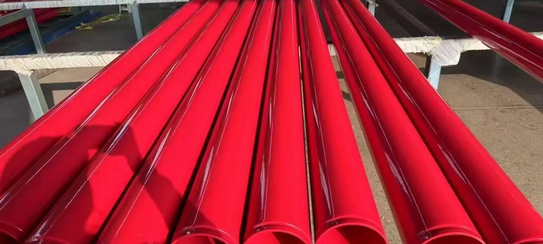
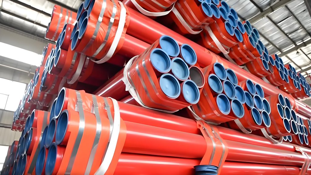
ASTM A135 Fire Sprinkler Pipes
The Definitive Engineering Compendium for ASTM A135 Electric-Resistance-Welded (ERW) Steel Fire Protection Piping Systems: Mechanical Profiles, Complete Schedule Matrices, Coating Protocols, and NFPA Compliance Frameworks.
2. Comparative Analysis
3. Production Parameters
4. Schedule Dimensions
5. Mechanical & Tolerance
6. Corrosion Inhibitors
1. Regulatory & Functional Overview of ASTM A135 Carbon Steel Pipe
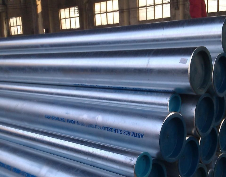
In automated life-safety infrastructure, ASTM A135 represents the standard specification issued by the American Society for Testing and Materials for Electric-Resistance-Welded (ERW) Steel Pipes. Specifically optimized for fluid conveyance, gas distribution, and structural water loops, ASTM A135 pipelines fulfill a vital role within commercial, industrial, and municipal infrastructure. In the field of active fire suppression, statistics confirm that over 70% of global fire suppression layouts utilize a wet-pipe design, with ASTM A135 serving as a reliable structural framework.
The production of ASTM A135 ERW pipe involves cold-forming flat strips of refined carbon steel into a continuous cylindrical shape, followed by long-axis high-frequency induction welding. To ensure long-term mechanical safety under internal fluid pressures, Grade B pipes undergo a specialized post-weld thermal treatment phase. This metallurgical step tempers the weld zone, eliminating untempered martensite formations and establishing uniform ductility across the profile cross-section.
Critical Architectural Integration Limits:
Unlike generic structural tubes, ASTM A135 sprinkler piping complies with strict structural guidelines under NFPA 13 (Standard for the Installation of Sprinkler Systems) and NFPA 14. It provides certified wall thicknesses, reliable mill test pressures, and verified corrosion resistance margins essential for high-velocity fire suppression loops.
2. Standards Comparison: ASTM A135 vs. ASTM A53 vs. ASTM A795
Specifying engineers must evaluate the precise technical trade-offs between general fluid conveyance tubes and specialized fire-protection pipes. The detailed comparison matrices below define the manufacturing methods, application scopes, and economic factors across these standard frameworks.
Table 1: Technical Comparison: ASTM A135 vs. ASTM A53
| Feature Definition | ASTM A135 Standard Framework | ASTM A53 Standard Framework |
|---|---|---|
| Manufacturing Process | Electric-Resistance-Welded (ERW) exclusively. | ERW, Seamless, and Type F Furnace-Butt-Welded. |
| Pressure Capacity | Optimized for light to medium fluid handling regimes. | High-pressure capacity across chemical and thermal sectors. |
| Economic Assessment | Highly cost-effective for structural distributions. | Higher production costs due to seamless billet requirements. |
| Primary Applications | Fire protection loops, low-pressure gas, water distribution. | High-pressure steam, oil and gas piping, structural columns. |
Table 2: Design Complementarity: ASTM A135 vs. ASTM A795
| Analytical Aspect | ASTM A135 Pipe Specification | ASTM A795 Pipe Specification |
|---|---|---|
| Scope Specialization | Broad liquid/gas conveyance standard applied to fire safety systems. | Dedicated standard engineered exclusively for fire sprinkler systems. |
| Structural Grades | Grade A and Grade B (heat treated). | Grade A and Grade B (Furnace butt-welded or ERW). |
| System Adaptability | Highly customizable across industrial pipeline frameworks. | Strictly standardized for ease of installation by global contractors. |
3. Technical Parameters & Manufacturing Substrate Framework
The production of ASTM A135/A795 certified sprinkler piping complies with rigorous material standards. This structural integrity allows the pipe to handle rapid dynamic pressures when pneumatic valves actuate or high-yield booster pumps trigger.
Table 3: Comprehensive Production Matrix & Processing Capacities
| Manufacturing Metric | Compliance Specification Boundaries |
|---|---|
| Standard Designations | ASTM A135 / ASTM A795 Fire Protection Sprinkler Pipe |
| Approval Endorsements | UL Listed (US & Canada) & FM Approved (2″ NPS – 8″ NPS Profiles) |
| Dimensional Span | Outer Diameters from $\Phi 21.3\text{ mm}$ to $\Phi 219.1\text{ mm}$ (Nominal 1/2″ through 8″ NPS) |
| Wall Profiles Engineered | Schedule 7 (Lightwall), Schedule 10, Schedule 30, and Schedule 40 (Standard-Wall) |
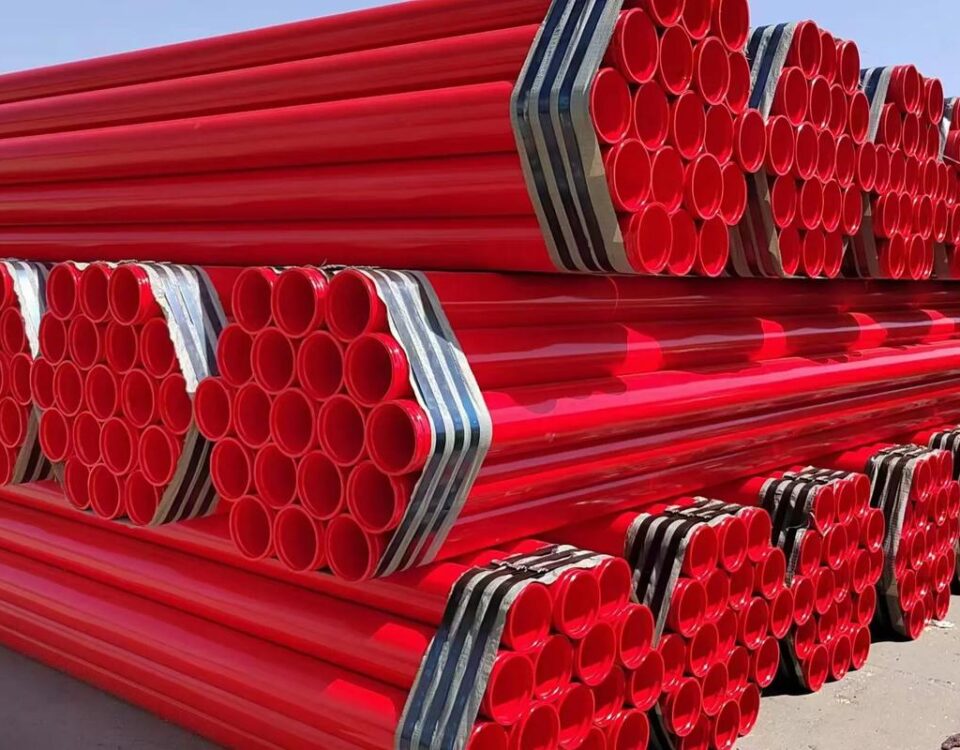
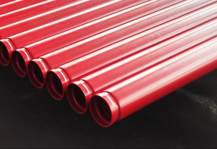
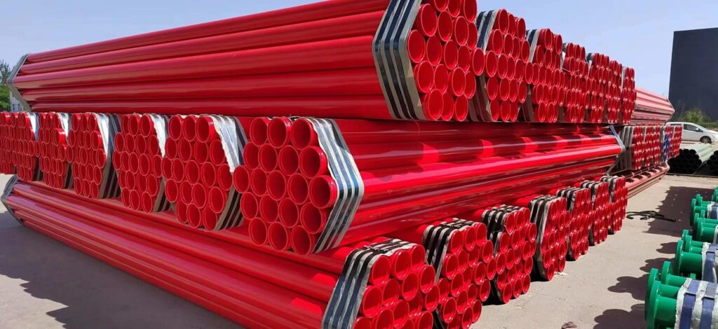
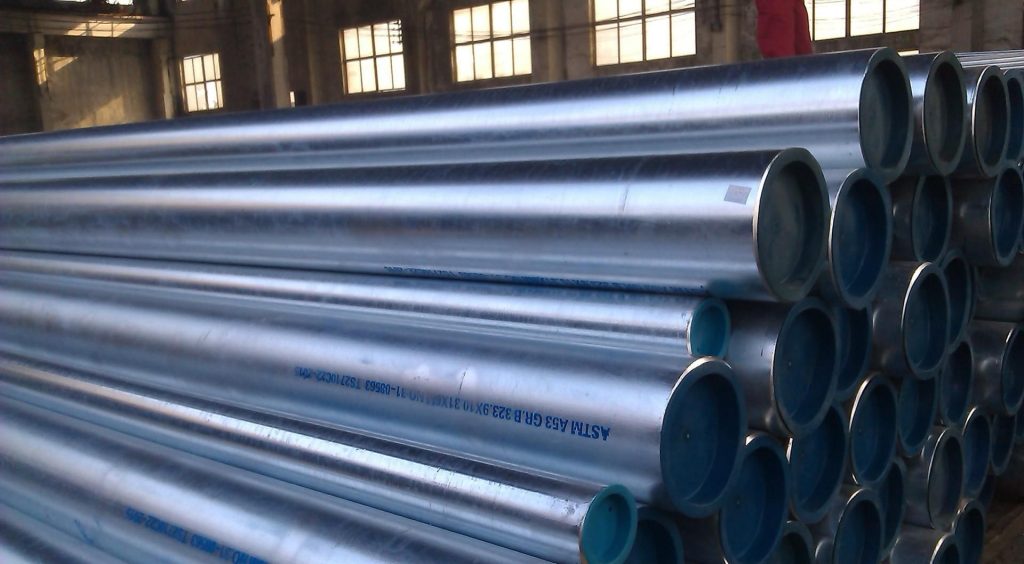
| Anti-Corrosive Processing | Hot-Dip Galvanizing, Architectural Powder Coating, Protective Painting, or Black MIC Guard |
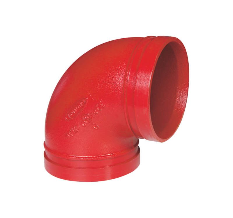
| End State Configurations | Precision Roll Grooved, Square Cut Plain End (PE), Screwed & Socketed / Threaded Coupling |
4. Exhaustive Dimensional & Structural Weight Reference Charts
The engineering reference datasets below outline outside diameters, wall thickness profiles, shipping tolerances, and hydrostatic mill verification pressures across Schedule 10, 40, and 7 systems.
Table 4: ASTM A135 Schedule 10 (Lightwall) Mechanical Metric Data
| NPS (Inch) | Nominal OD (mm) | Nominal ID (Inch) | Wall Thickness (mm) | Nominal Weight (kg/m) | Pcs per Bundle | Mill Test Pressure (MPa) |
|---|---|---|---|---|---|---|
| 3/4″ | 26.8 | 0.884 | 2.11 | 1.28 | 91 | 17.24 |
| 1″ | 33.5 | 1.097 | 2.77 | 2.09 | 91 | 17.24 |
| 1 1/4″ | 42.2 | 1.442 | 2.77 | 2.70 | 61 | 16.55 |
| 1 1/2″ | 48.3 | 1.682 | 2.77 | 3.11 | 61 | 14.48 |
| 2″ | 60.3 | 2.157 | 2.77 | 3.93 | 37 | 11.72 |
| 2 1/2″ | 73.0 | 2.635 | 3.05 | 5.26 | 30 | 10.34 |
| 3″ | 88.9 | 3.260 | 3.05 | 6.45 | 19 | 8.27 |
| 3 1/2″ | 101.6 | 3.760 | 3.05 | 7.41 | 19 | 6.89 |
| 4″ | 114.3 | 4.260 | 3.05 | 8.36 | 19 | 6.21 |
| 5″ | 141.3 | 5.292 | 3.40 | 11.58 | 10 | 5.86 |
| 6″ | 168.3 | 6.357 | 3.40 | 13.84 | 10 | 5.02 |
| 8″ | 219.1 | 8.249 | 4.80 | 25.41 | 7 | 4.26 |
Table 5: ASTM A135 Schedule 40 (Standard-Wall) Mechanical Metric Data
| NPS (Inch) | Nominal OD (mm) | Nominal ID (Inch) | Wall Thickness (mm) | Nominal Weight (kg/m) | Pcs per Bundle | Mill Test Pressure (MPa) |
|---|---|---|---|---|---|---|
| 1/2″ | 21.3 | 0.622 | 2.77 | 1.27 | 127 | 17.20 |
| 3/4″ | 26.8 | 0.824 | 2.87 | 1.68 | 91 | 17.20 |
| 1″ | 33.5 | 1.049 | 3.38 | 2.50 | 61 | 17.20 |
| 1 1/4″ | 42.2 | 1.380 | 3.56 | 3.38 | 61 | 17.20 |
| 1 1/2″ | 48.3 | 1.610 | 3.68 | 4.05 | 37 | 17.20 |
| 2″ | 60.3 | 2.067 | 3.91 | 5.43 | 24 | 16.08 |
| 2 1/2″ | 73.0 | 2.469 | 5.16 | 8.62 | 19 | 17.20 |
| 3″ | 88.9 | 3.068 | 5.49 | 11.28 | 13 | 15.30 |
| 3 1/2″ | 101.6 | 3.548 | 5.74 | 13.56 | 10 | 14.00 |
| 4″ | 114.3 | 4.026 | 6.02 | 16.06 | 10 | 13.06 |
| 5″ | 141.3 | 5.047 | 6.55 | 21.76 | 7 | 11.50 |
| 6″ | 168.3 | 6.065 | 7.11 | 28.34 | 7 | 10.48 |
| 8″ | 219.1 | 7.981 | 8.18 | 36.90 | 5 | 7.96 |
Table 6: ASTM A135/A795 Schedule 7 (Ultra-Lightwall) Dimensional Profile
| NPS (Size) | Nominal OD (Inch) | Nominal ID (Inch) | Wall Thickness (Inch) | Nominal Weight (lbs/ft) | Est. 21′ Lift Weight (lbs) |
|---|---|---|---|---|---|
| 2″ | 2.375″ | 2.207″ | 0.084″ | 2.06 | 1,054 |
| 2 1/2″ | 2.875″ | 2.703″ | 0.086″ | 2.56 | 1,613 |
| 3″ | 3.500″ | 3.314″ | 0.093″ | 3.39 | 1,352 |
| 4″ | 4.500″ | 4.304″ | 0.098″ | 4.61 | 1,839 |
5. Mechanical Performance Limits & Geometric Forging Tolerances
To prevent dimensional distortion during installation or system operation, manufacturing runs must comply with the mechanical property thresholds and geometric tolerances outlined below.
Table 7: Mechanical Strength and Testing Profiles
| Performance Metric | ASTM A135 Grade A Baseline | ASTM A135 Grade B Baseline |
|---|---|---|
| Ultimate Tensile Strength | 48,000 psi (330 MPa) min | 60,000 psi (415 MPa) min |
| Minimum Yield Point | 30,000 psi (205 MPa) min | 35,000 psi (240 MPa) min |
| Outside Diameter (OD) Tolerance | ±1% from nominal specification | ±1% from nominal specification |
| Wall Thickness Variance | -12.5% maximum under nominal | -12.5% maximum under nominal |
| Straightness Criteria | Reasonably straight commercial run | Reasonably straight commercial run |
6. Advanced Corrosion Protection: MIC Guard Technology Integration
Internal pipe wall corrosion is a primary cause of hydraulic resistance increases and structural pinning leaks within fire protection installations. Stagnant oxygenated water configurations accelerate Microbiologically Influenced Corrosion (MIC). This phenomenon occurs when bacterial colonies form inside the distribution network, generating acidic localized environments that corrode bare carbon steel.
To address this issue, premium ASTM A135 pipe runs feature specialized internal coatings like MIC Guard. This advanced water-based chemical emulsion forms an inert protective barrier along the inner steel surface. By preventing microbial adhesion and oxidation without affecting adjacent chemical substrates, it provides reliable protection for multi-material fire containment setups.
⚠️ FIELD THREADING SAFETY AND GAUGING NOTICE:
For unthreaded Schedule 10 configurations or threaded Schedule 40 runs, compliance dictates strict field threading checks. Improper thread depth or pitch can lead to system leaks. Always cross-verify field-cut threads with an authentic ANSI B1.20.1 thread gauge.
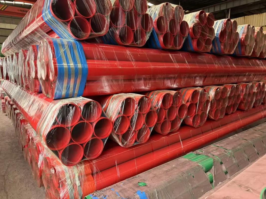
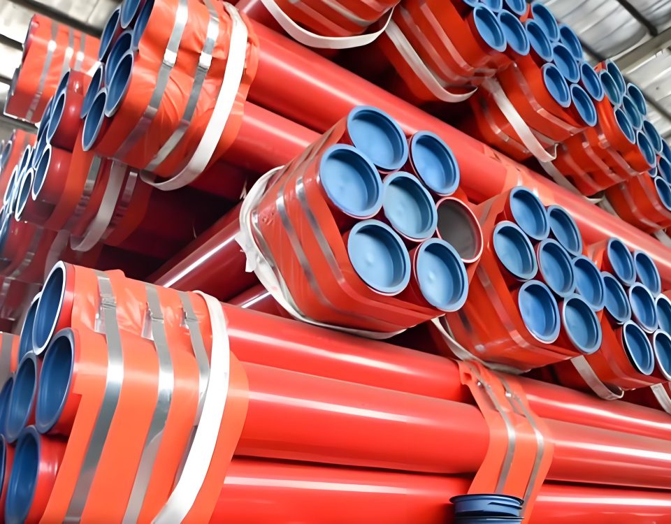
7. Global Logistics, Shipping Volumes, and Lift Weights
The table below provides accurate shipping bundle metrics for international freight calculations and overhead crane deployment scheduling at active construction locations.
Table 8: Export Lift Parameters (Standard 21-Foot / 6.4-Meter Shipping Configurations)
| Nominal Size (NPS) | Pcs Per Bundle Lift | Schedule 10 Lift Weight (lbs) | Schedule 40 Lift Weight (lbs) |
|---|---|---|---|
| 2″ | 37 / 24 | 2,051 | 1,840 |
| 2 1/2″ | 30 / 19 | 2,224 | 2,310 |
| 3″ | 19 / 13 | 1,732 | 2,069 |
| 4″ | 19 / 10 | 2,242 | 2,266 |
| 6″ | 10 / 7 | 1,953 | 2,792 |
| 8″ | 7 / 5 | 2,493 | 3,001 |
8. Industrial & Infrastructure Application Environments
ASTM A135 certified structural pipelines provide fire protection performance across demanding high-occupancy and critical infrastructure environments:
Mass Transit Logistics Nodes
Underground subway transit lines, airport passenger terminals, international deepwater seaports, and rail network hub systems.
Civil Structural Engineering
Complex vehicular tunnel structures, high-clearance highway bridges, deep subterranean parking basements, and multi-tier utility spaces.
Industrial Process Facilities
Secondary process loops, fluid handling distributions, thermal ventilation layouts, and general industrial plant water networks.
Optimize Your System Safety Metrics with Certified ASTM A135 Piping
Ensure project validation, complete design flexibility, and certified safety by incorporating precision-welded, UL-listed, and FM-approved technical carbon steel options.
Technical Documentation Database Ref: EN-ASTM-A135-A795-INDEX-2026 | Approved For Global Search Indexing and Engineering Redistribution.
9. Hydrostatic Pressure Testing Performance & Mill Verification Criteria
To guarantee absolute operational integrity during sudden high-pressure transients—such as fire pump activation, fast valve closures, or backflow preventer shifts—every linear meter of ASTM A135/A795 pipe undergoes meticulous pressure verification. Compliance with NFPA 13 necessitates that the piping substrate withstand internal hydrostatic pressures without displaying signs of structural weeping, seam dilation, or micro-fracturing.
During production, pipes are subjected to a factory mill hydrostatic test for a minimum duration of 5 seconds. For nominal pipe sizes spanning 2″ to 5″ within Schedule 10 configurations, hydrostatic verification is an absolute regulatory requirement, and non-destructive testing (NDT) cannot be substituted as an alternative.
Table 11: Production Line Hydrostatic Test Pressure Requirements
| Nominal Pipe Size (NPS) | Schedule 10 Test Pressure (MPa) | Schedule 40 Test Pressure (MPa) |
|---|---|---|
| 1/2″ to 1″ Profiles | 17.24 | 17.20 |
| 1-1/4″ to 1-1/2″ Profiles | 14.48 – 16.55 | 17.20 |
| 2″ to 3″ Profiles | 10.34 – 11.72 | 15.30 – 16.08 |
| 4″ to 6″ Profiles | 5.02 – 6.21 | 10.48 – 13.06 |
| 8″ Large-Bore Profiles | 4.26 | 7.96 |
10. Chemical Composition Boundaries & Metallurgical Substrate Matrix
The structural ductility, flattening capability, and high-frequency weld integrity of ASTM A135 pipe rely on strict limits for trace chemical elements. Controlling these elements ensures the steel profile remains malleable during roll-grooving procedures while maintaining structural hardness.
The presence of trace elements like phosphorus and sulfur must be tightly controlled; high concentrations can lead to structural embrittlement along the longitudinal heat-affected zone (HAZ). The table below outlines the maximum allowable element concentrations specified for Grade A and Grade B variants.
Table 12: Heat Analysis Chemical Element Threshold Limits (Max %)
| Steel Grade | Carbon (C) | Manganese (Mn) | Phosphorus (P) | Sulfur (S) |
|---|---|---|---|---|
| Grade A | 0.25% | 0.95% | 0.035% | 0.035% |
| Grade B | 0.30% | 1.20% | 0.035% | 0.035% |
11. Hydraulic Design Flow Friction Loss Variables & Roughness Metrics
When layout designers compile hydraulic calculations using specialized engineering software, the interior smoothness of the piping run directly affects the system’s overall friction loss. Fire protection engineers utilize the Hazen-Williams empirical formula to evaluate pressure drops across the structural grid.
The roughness coefficient ($C$-value) scales with the quality of the interior anti-corrosive coating applied to the carbon steel base. Untreated or oxidized black steel profiles generate more internal turbulence than options coated with specialized waxy emulsions or internal fusion-bonded epoxies.
Table 13: Hazen-Williams Roughness Coefficients ($C$-Values) for Design Formulations
| Piping System Coating Configuration | NFPA 13 Standard $C$-Value | Absolute Hydraulic Roughness ($\epsilon$, mm) |
|---|---|---|
| MIC Guard / Water-Based Emulsion Coated Steel | 120 – 130 | 0.040 |
| Hot-Dip Galvanized Zinc Layer (Wet Systems) | 120 | 0.150 |
| Hot-Dip Galvanized Zinc Layer (Dry / Preaction Systems) | 100 | 0.250 |
| Coroded / Deteriorated Black Steel Baseline | 100 | 0.450 |
12. Mechanical Destructive Quality Testing Framework
To confirm structural ductility and verify that the longitudinal ERW seam maintains uniform integrity under structural loads, production run samples are subjected to rigorous destructive physical testing.
The primary verification methods include the flattening test and the cold bend test:
- The Flattening Test: Structural ring samples cut from the ends of selected pipes are flattened between parallel plates. The weld seam is positioned at 90° or 0° relative to the direction of the applied force. The material must undergo full displacement without developing structural fractures or fusion separations along the seam.
- The Cold Bend Test: For pipe profiles with nominal diameters equal to or less than 2″ NPS, full-scale cross-sections are bent cold through an angle of 90° around a cylindrical mandrel. The pipe run must not show signs of cracking or seam separation.
Table 14: Quality Testing Schedule and Sampling Rates
| Test Classification | Sampling Evaluation Cadence | Pass Status Metrics |
|---|---|---|
| Longitudinal Seam NDT | 100% of manufactured pipe runs via ultrasonic/eddy current methods. | Zero defect signals. |
| Flattening Protocol | One sample selected from each lot of 400 lengths or fewer per size run. | No structural fissures. |
| Hydrostatic Proofing | Every individual pipe run length, unless bypassed by approved NDT alternates. | Zero structural pressure drops. |
13. Maintenance Audits & Field Inspection Frameworks
To maintain structural integrity after field handover, automated fire suppression layouts require regular inspections according to NFPA 25 (Standard for the Inspection, Testing, and Maintenance of Water-Based Fire Protection Systems). System operators must check for exterior scale accumulation, evaluate the condition of hangers, and perform internal flushing procedures to clear micro-sediment build-up.
Table 15: NFPA 25 Inspection Interval Checklist for Piping Substrates
| Inspection Cadence | Target Assessment Sub-Matrix Location | Required Rectification Measures |
|---|---|---|
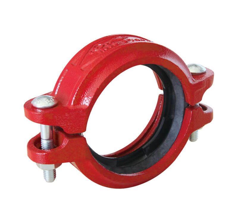
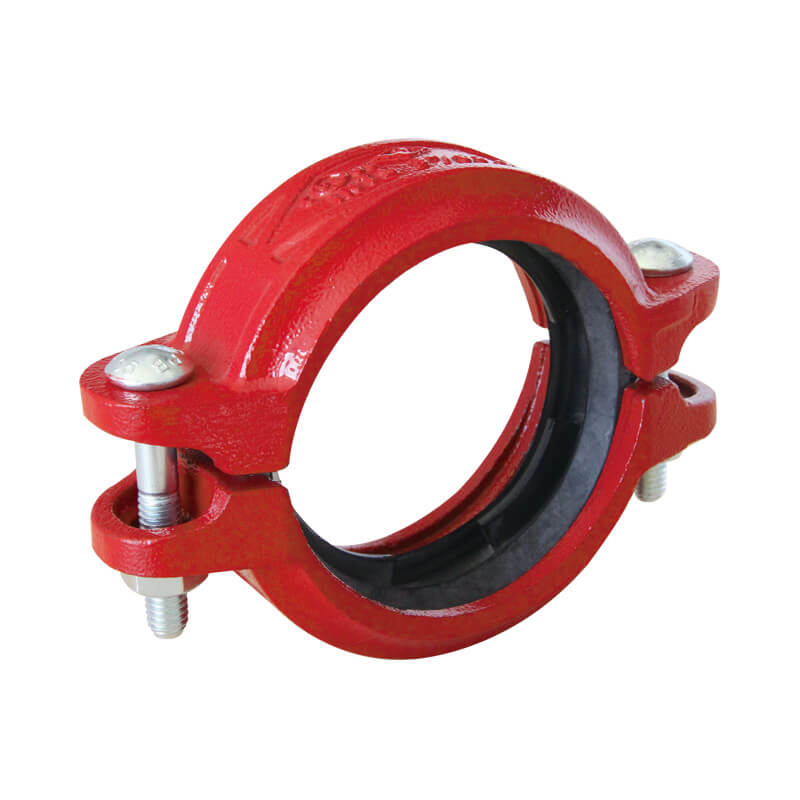
| Annual Cycle | Exterior pipe surfaces, seismic bracing, mechanical couplings, and sprinkler head fittings. | Clear surface scaling, realign structural supports, and replace worn gaskets. |
| 5-Year Cycle | Internal pipe wall diagnostic evaluation to inspect for microbial activity (MIC) or internal blockages. | Perform system flushing, introduce biostatic inhibitors, or replace damaged sections. |
