Classification, production process and mechanical properties of seamless steel pipes
July 5, 2022
Steel pipes are cylindrical tubes
July 8, 2022This paper deals with the deformation of precision seamless tubes during the cold drawing process, using Finite Element Methods. The
value of strain obtain by stereology measurement of degree grain boundaries deformation are compared with simulation result for each
drawing pass. The material chosen was the E235 and E355 steel grade, which is drawn from the initial dimension of Φ70 x 6.3 mm to the final
dimension of Φ 50 x 3.75 mm by two passes. FEM Software DEFORM 2D with the Lagrangian method is used to numerical analyses of the cold
drawing process.
1 Introduction
Cold drawing technology used for manufacturing of precision seamless tube depends on many factors. Cold forming process parameters, tool geometry initial and final tube dimension are selected to ensure a high quality of the tubes. In order to achieve the final diameter and wall thickness, tubes are reduced successively in several cold drawing steps.
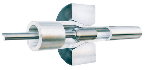
This can be done by either drawing the tube through a die and by adding a plug, which results in better defined wall thickness and inner surface quality. Cold drawing using a fixed plug is a versatile technology that is used usually in the Železiarne Podbrezová ironworks company. The experiment results of this company are compared with the numerical simulation described in this paper.
2 Experimental Material
In this work, steel grade E235 and E355 (ferritic-pearlitic carbon steel, see Table was considered; as a feedstock for cold drawing, hot rolled tube with dimensions of 70 x 6.3 mm was selected. Mechanical properties of E235 steel are as follows: yield stress Re = (226 245) MPa, tensile strength Rm 343 441) MPa, ductility A5 24 , mechanical properties of E355 steel are as follows: yield stress Re = (335 355) MPa, tensile strength Rm 490 630) MPa, ductility A5 24

2.1 Workpiece and tools of material modelling
As the temperature stays lower in cold drawing, the material properties do not vary and can therefore be supposed to by independent of the temperature variation. As the material behavior is considered temperature independent, the power law constitutive equation of
material plastic properties can be used eq. 1. Where represent the equivalent effective plastic strain represent the effective plastic strain rates, and material parameters are determined by means of tensile tests [1, 5], they are listed in Table 2.
The tube material was considered as plastic, the hardening is assumed as isotropic, and yield function type is set as Von Mises.
The geometry of the tube has been meshed. The eight elements are across the wall of the tube in first pass the six are in second pass Fig. 5. This mesh of workpiece is sufficient for accuracy and does not need to be re-mesh procedure during the calculation.
The forming tools, (mandrel and die) was considered as rigid bodies. The mesh of tools did not need to be generated for simulation.

2.2 Numerical simulation
DEFORM 2D and the Lagrangian calculation has been set for numerical simulation of cold drawing technology, according to the tool dimension given on Table 3. The initial axisymmetric geometric configuration has been set. The drawing velocity was 9 m.min-1 for all passes in experimental drawing and simulation boundary conditions. The friction model between the tools and the material was chosen to be a shear-type with the value of 0.08.
The data interpolation functionality was used to set the second pass calculation. The final data from first pass was transfer, and to set second pass. This data transformation must be done, because drawing technology were performed without an interoperative annealing.
2.3 Tube Drawing Technology
The main production steps for tube cold drawing technology in Železiarne Podbrezová are
as follows:
• feedstock pre-processing (hot rolled tube with dimensions of Ø70 x 6.3 mm).
• cold/hot pointing of tube ends (target diameter 40 mm).
• chemical treatment of the tube (pickling, phosphating, lubrication).
• cold drawing (see Tab. 3 for details).
• intermediate annealing and final annealing in protective atmosphere.
• final conditioning.
• surface inspection, packaging, rust-proofing.
• dispatch.
The final reduction of the tube area for two-pass technology (from Ø70 x 6. 3 mm to Ø50 x 3.75 mm) was 57.78 %; the value was divided rather uniformly among all passes
(see Table 3). Calculation of tube cross-section (area) reduction:
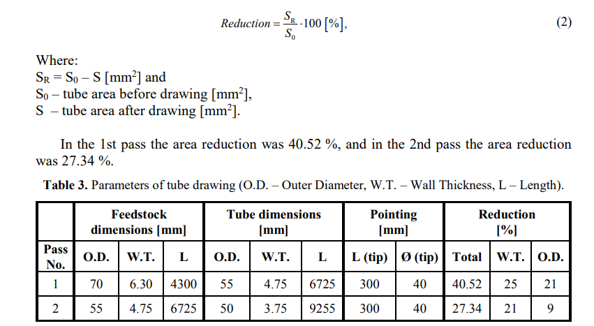
Local plastic deformation of tube was analyzed. During subsequent drawing steps, the tube undergoes plastic deformation. Final geometry and properties of deformed tubes depends on strain value. It is possible to investigate change of material structure and predict plastic deformation.
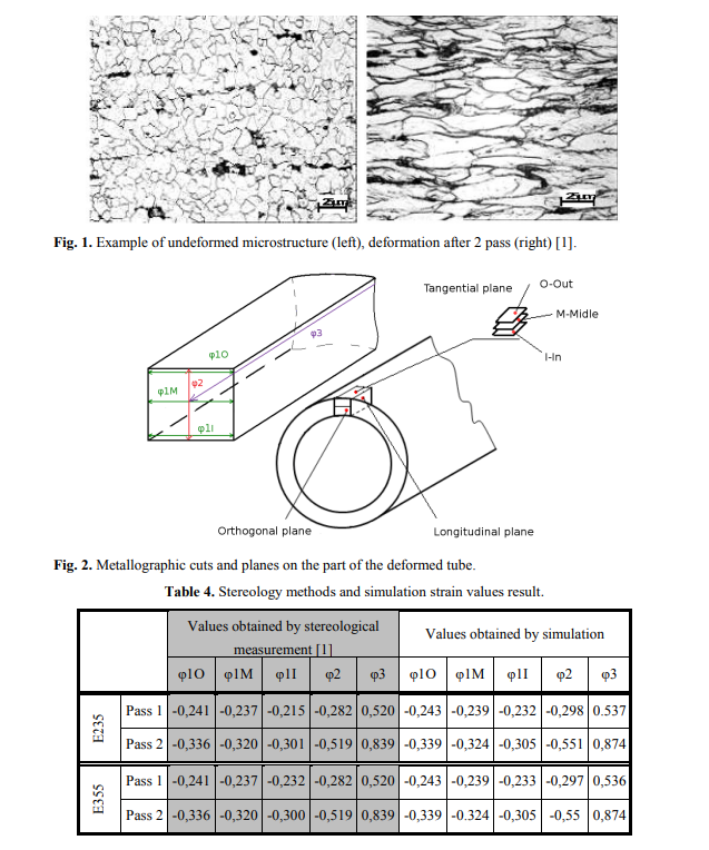
The microstructure of each pas was observed in orthogonal tangential and longitudinal plane of deformed tube with about 500x magnification of light microscope and metallographic cut Fig1. Tangential metallographic cut is don three times. On the inside of the pipe surface “I”, on the outside of the pipe surface “O” and on the middle ”M” of the pipe wall Fig. 2. Due to plastic deformation, the structure anisotropy increased – grain
boundaries orientation in deformed place of piece was observed. The local strain in analyzed place was obtained by stereological measurement of degree of grain boundaries orientation [4, 6]. The anisotropic microstructure was decomposed into isotropic and planar oriented components using quantitative metallography [3, 4] (Saltykov stereology methods with oriented test lines). Measured and calculated parameters of local plastic deformation in deformed zone are listed in Table 4.

-steel-pipe.jpg)
