
EN 10312 Welded Stainless Steel Tubes
June 22, 2026
DIN 1629 Seamless Carbon Steel Pipes
Premium Industrial Standard
DIN 1629 Seamless
Non-Alloy Steel Pipes
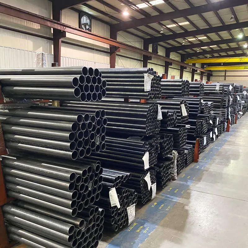
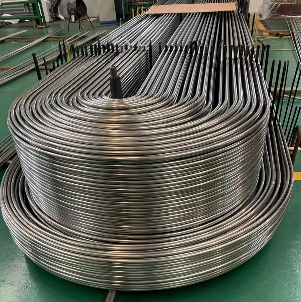
High-performance structural & thermal circular tubes engineered for extreme chemical processing, boiler operations, and plant machinery construction.
✓ OD: 10.2mm – 660mm
✓ WT: 1.0mm – 30mm
⚠ Temp Limit < 300°C
Max Yield Stress
Max Length
Size Matrix
Deoxidization
1. DIN 1629 Specification Framework & Scope
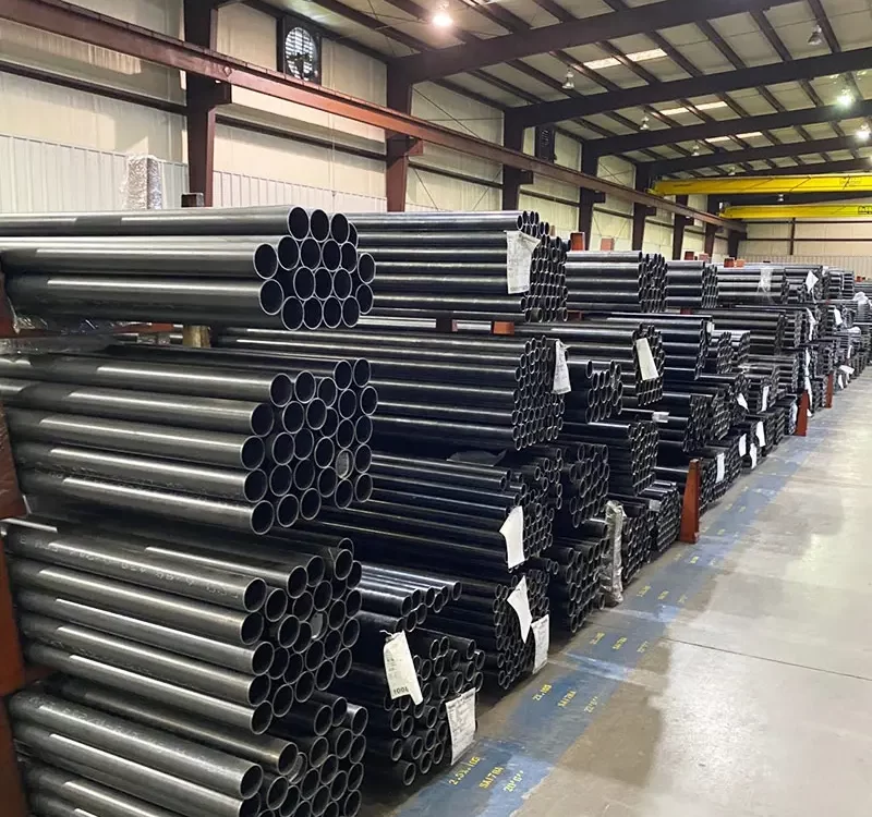
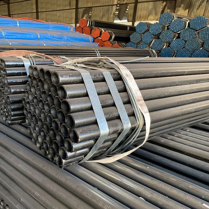
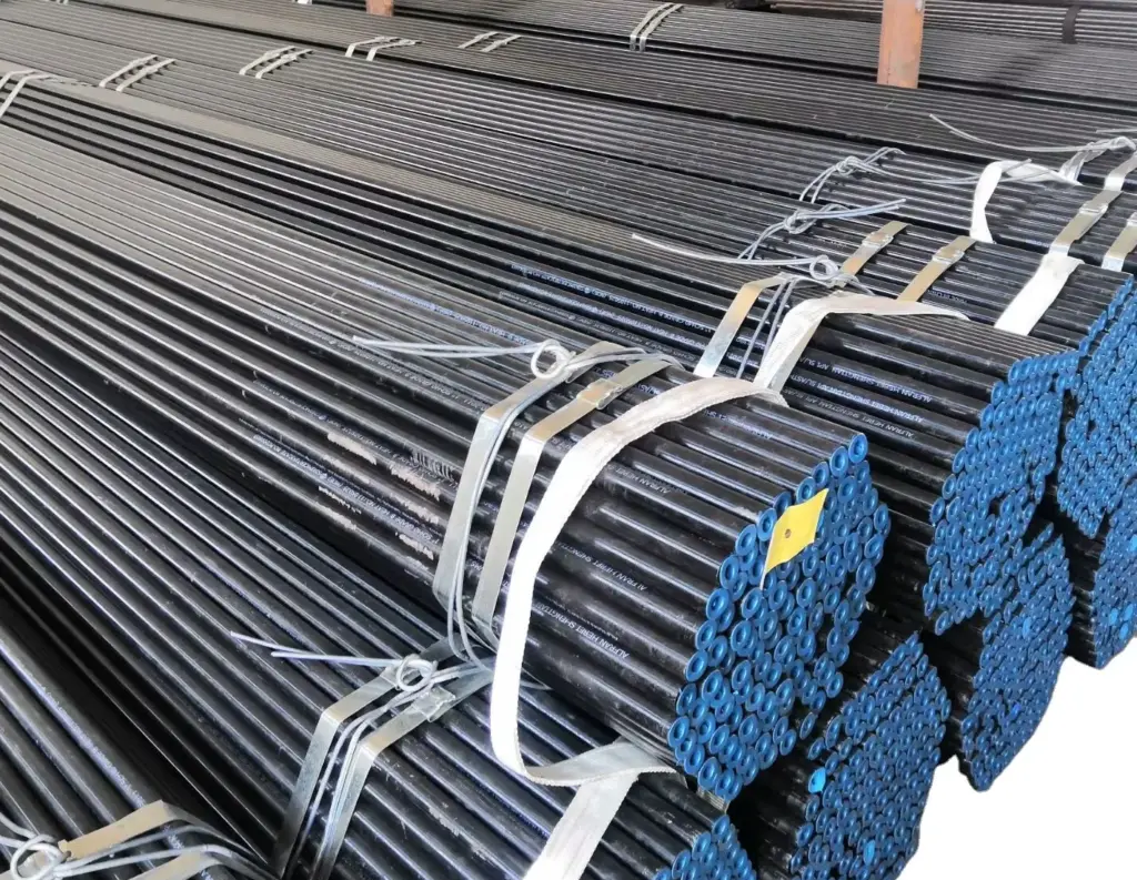
DIN 1629 is a highly rigorous European regulatory standard specifying the structural design metrics and quality controls for seamless circular tubes made of non-alloy steels with special quality requirements. These highly engineered pipelines are critical mechanical structural components optimized for operation under complex thermal and fluid dynamic pressures with zero arbitrary design limiting working pressure values.
The operational environment of DIN 1629 non-alloy tubes dictates high reliability under elevated thermal profiles, establishing strict engineering design limitations requiring continuous operational thresholds to remain securely below 300°C (572°F). This specification makes them distinct from high-temperature superalloys, targeting instead mid-tier industrial applications where ductile management and processing predictability are required.
⚠ CRITICAL APPLICATION RANGE CRITERIA
Due to the unalloyed structure of the steel substrate, these elements are highly suitable for basic system deployment in major engineering spheres including: industrial chemical manufacturing plant networks, pressurized boiler auxiliary setups, complex vessel construction, sub-surface utility pipework infrastructure, and high-impact structural automotive or machine building assemblies.
Technical Deployment Overview
- High-Impact Outdoor Deployment: Features exceptional impact loading capacities under extreme climatic cycles.
- Advanced Weldability Profiles: Optimized for manual gas fusion, traditional electric arc, automated flash-butt, and specialized pressure methods.
- Forming Adaptability: Excellently handles localized secondary cold forming, expand-flaring, and continuous radius bending.
1.1 Unified Core Technical Procurement Framework
| Technical Property Category | Standard Regulatory Metric Value | Engineering Metric Unit |
|---|---|---|
| Manufacturing Manufacturing Method | Seamless (SMLS) Hot Finished / Cold Worked Base | Process Designation |
| Outer Diameter (OD) Scope | 10.2 to 660.0 | mm |
| Wall Thickness (WT) Scope | 1.0 to 30.0 | mm |
| Max Integrated Unit Length | 14,000 (Custom Cut-to-length Available) | mm |
| Core Material Structural Classification | Unalloyed Carbon High-Quality Carbon Steel Elements | Metallurgical Class |
| Allowable Internal Loading Stress Limit | Uncapped (Calculated per wall thickness configuration) | MPa / Bar Pressures |
| Non-Destructive Testing Requirements | 100% Electromagnetic Hydro-static / Eddy Current Equivalent | Quality Control Target |
2. Metallurgical Matrix & Chemical Composition
The chemical composition profiles of DIN 1629 grades are carefully calibrated to ensure balance between structural rigidity, high-yield elasticity, and optimized low-carbon weldability. Controlling carbon equivalent values prevents the formation of localized martensitic structures inside heat-affected welding zones, maintaining high mechanical ductility during installation.
| Steel Grade Name | Material Number ID | Deoxidization Type Standard | Chemical Composition Limits (% by Mass Maximum Specified Value) | ||||
|---|---|---|---|---|---|---|---|
| C | P | S | N¹ | Al Addition Fix | |||
| St 37.0 | 1.0254 | R (Killed Steel) | 0.17 | 0.040 | 0.040 | 0.009² | Not Applicable |
| St 44.0 | 1.0255 | R (Killed Steel) | 0.21 | 0.040 | 0.040 | 0.009² | Not Applicable |
| St 52.0³ | 1.0421 | RR (Fully Killed) | 0.22 | 0.040 | 0.035 | — | Al Total ≥ 0.020% |
¹ Nitrogen content statement: If elements such as Aluminum, Titanium or Vanadium are added as nitrogen-fixing agents, nitrogen maximum value boundaries do not apply.
² Atmospheric nitrogen limits variation: A maximum value up to 0.012% N is permitted under cast analysis if thickness values are thin.
³ St 52.0 microalloy structural design contains specialized components: Silicon (Si) max 0.55%, Manganese (Mn) max 1.60% to control granular refinement structures.
3. Structural Mechanical Performance Specifications
The mechanical performance parameters of DIN 1629 elements vary based on the specific steel grade and localized wall thickness metrics. As the cross-sectional wall profile increases, standard material cooling parameters adjust, resulting in subtle modifications to lower yield boundary limitations.
| Steel Grade Symbol | Material Number ID | Minimum Upper Yield Stress \(R_{eH}\) (MPa) vs Wall Thickness (mm) | Ultimate Tensile Strength \(R_m\) (MPa) | Minimum Fracture Elongation \(A_5\) (%) | |||
|---|---|---|---|---|---|---|---|
| ≤ 16mm | 16mm – 40mm | 40mm – 65mm | Longitudinal | Transverse | |||
| St 37.0 | 1.0254 | 235 | 225 | 216 | 350 to 480 | 25 | 23 |
| St 44.0 | 1.0256 | 275 | 265 | 255 | 420 to 550 | 21 | 19 |
| St 52.0 | 1.0421 | 355 | 345 | 335 | 500 to 650 | 21 | 19 |
For specialized cold-drawn tubes delivered under NBK protective heat-shield annealing parameters, a 20 N/mm² downward tolerance adjustment for yield parameters and a 10 N/mm² adjustment for ultimate tensile parameters are code-permissible.
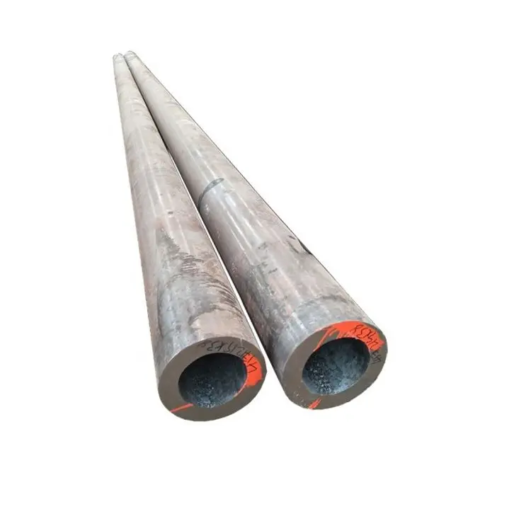
4. Dimensional Tolerances & Execution Criteria
Dimensional accuracy limits vary depending on the processing methodology selected. Hot rolling, surface peeling, and precision cold drawing involve distinct structural tolerance capabilities.
| Execution Finish Route | Operational Range Parameter | Outer Diameter (OD) Tolerance | Wall Thickness (WT) Tolerance Bound |
|---|---|---|---|
| Standard Hot-Rolled Tube | OD ≤ 80 mm | ± 0.4 mm | ± 0.7 mm (For WT < 12 mm) |
| OD > 80 mm | ± 0.5% of nominal OD | ± (5% × WT + 0.1 mm) for WT ≥ 12 mm | |
| Hot-Rolled Peeled Tube Variant | All diameters combined | + 0.25 mm / – 0 mm | ± 0.8 mm (For WT < 12 mm) |
| All diameters combined | + 0.25 mm / – 0 mm | ± (5% × WT + 0.2 mm) for WT ≥ 12 mm | |
| Cold-Worked Precision Tube (Draw / Roll) | OD < 40 mm | + 0.30 mm / – 0 mm | ± 0.30 mm (For WT < 6 mm) |
| OD 40 mm – 80 mm | + 0.35 mm / – 0 mm | ± 0.35 mm (For WT 6 mm – 8 mm) | |
| OD > 80 mm | + 0.40 mm / – 0 mm | ± 0.40 mm (For WT > 8 mm) |
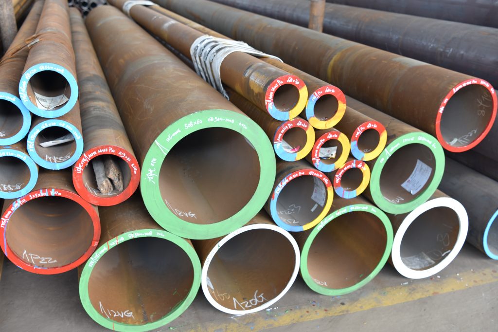
5. Full DIN 1629 SMLS Production Dimensional Cross-Section Matrix
The comprehensive table below cross-references outer diameter (OD) configurations with design wall thickness (WT) metrics. Available combinations are denoted by tracking dots (●).
| OD (mm) | 1.6 | 1.8 | 2.0 | 2.3 | 2.6 | 2.9 | 3.2 | 3.6 | 4.0 | 4.5 | 5.0 | 5.6 | 6.3 | 7.1 | 8.0 | 10.0 | 12.5 | 16.0 | 20.0 | 25.0 | 30.0 |
|---|---|---|---|---|---|---|---|---|---|---|---|---|---|---|---|---|---|---|---|---|---|
| 10.2 | ● | ● | ● | ● | ● | — | — | — | — | — | — | — | — | — | — | — | — | — | — | — | — |
| 13.5 | ● | ● | ● | ● | ● | ● | ● | — | — | — | — | — | — | — | — | — | — | — | — | — | — |
| 16.0 | ● | ● | ● | ● | ● | ● | ● | ● | — | — | — | — | — | — | — | — | — | — | — | — | — |
| 17.2 | ● | ● | ● | ● | ● | ● | ● | ● | ● | — | — | — | — | — | — | — | — | — | — | — | — |
| 21.3 | ● | ● | ● | ● | ● | ● | ● | ● | ● | ● | — | — | — | — | — | — | — | — | — | — | — |
| 25.4 | — | ● | ● | ● | ● | ● | ● | ● | ● | ● | ● | — | — | — | — | — | — | — | — | — | — |
| 26.9 | — | ● | ● | ● | ● | ● | ● | ● | ● | ● | ● | ● | — | — | — | — | — | — | — | — | — |
| 33.7 | — | — | ● | ● | ● | ● | ● | ● | ● | ● | ● | ● | ● | — | — | — | — | — | — | — | — |
| 42.4 | — | — | ● | ● | ● | ● | ● | ● | ● | ● | ● | ● | ● | ● | — | — | — | — | — | — | — |
| 48.3 | — | — | — | ● | ● | ● | ● | ● | ● | ● | ● | ● | ● | ● | ● | — | — | — | — | — | — |
| 60.3 | — | — | — | — | ● | ● | ● | ● | ● | ● | ● | ● | ● | ● | ● | ● | — | — | — | — | — |
| 76.1 | — | — | — | — | — | ● | ● | ● | ● | ● | ● | ● | ● | ● | ● | ● | ● | — | — | — | — |
| 88.9 | — | — | — | — | — | — | ● | ● | ● | ● | ● | ● | ● | ● | ● | ● | ● | ● | — | — | — |
| 114.3 | — | — | — | — | — | — | — | ● | ● | ● | ● | ● | ● | ● | ● | ● | ● | ● | ● | — | — |
| 139.7 | — | — | — | — | — | — | — | — | ● | ● | ● | ● | ● | ● | ● | ● | ● | ● | ● | ● | — |
| 168.3 | — | — | — | — | — | — | — | — | — | ● | ● | ● | ● | ● | ● | ● | ● | ● | ● | ● | ● |
| 219.1 | — | — | — | — | — | — | — | — | — | — | ● | ● | ● | ● | ● | ● | ● | ● | ● | ● | ● |
| 323.9 | — | — | — | — | — | — | — | — | — | — | — | — | ● | ● | ● | ● | ● | ● | ● | ● | ● |
| 406.4 | — | — | — | — | — | — | — | — | — | — | — | — | — | — | ● | ● | ● | ● | ● | ● | ● |
| 508.0 | — | — | — | — | — | — | — | — | — | — | — | — | — | — | — | ● | ● | ● | ● | ● | ● |
| 660.0 | — | — | — | — | — | — | — | — | — | — | — | — | — | — | — | — | ● | ● | ● | ● | ● |
Note: Non-standard dimensional combinations can be formulated via specialized cold elongation parameters based on custom project engineering constraints.
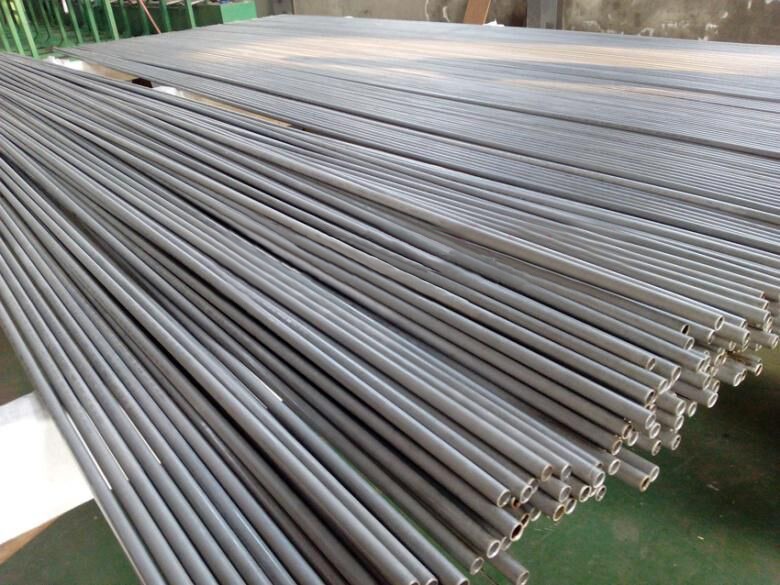
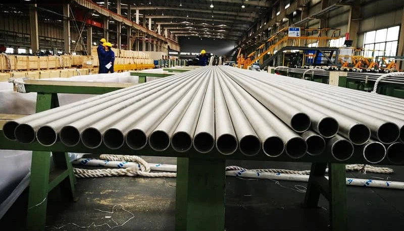
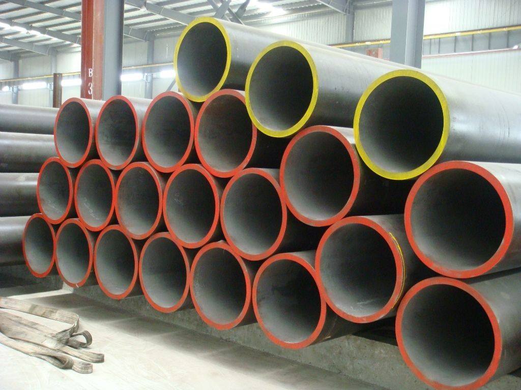
6. Custom Processing, Machining & Finishing Capabilities
To streamline field installation and reduce on-site structural adaptation costs, we provide an extensive array of secondary processing, machining, and protective coating services for DIN 1629 unalloyed carbon steel pipes.
Mechanical Profile Machining
Full support for precise geometric modifications, including orthogonal square cutting, calibrated bevel cutting (30°/45° configurations for field welding), precise mechanical hole drilling, structural slot punching, and specialized roll grooving for rapid coupling integration.
Deformation & End Forming
Advanced end forming capabilities to meet custom assembly requirements. Services include precise cold bending, continuous swaging, outer wall expansion flaring, structural tapering, and thread chasing per international thread parameters.
Anti-Corrosive Surface Finishing
Comprehensive protection profiles for transport and long-term storage. Options include standard industrial black varnishing, surface oiling, high-durability hot-dip galvanizing, and specialized multi-layer epoxy linings.
| End Style Classification | Processing Specification Limits | Joint Integration Mode Compatibility |
|---|---|---|
| Plain End / Square Cut | Perpendicularity deviation < 0.5 mm facing edge | Compression sleeves, specialized slip-on flanges |
| Bevelled End Arrangement | 30° angle (+5°/-0°) with 1.6 mm root face matrix (±0.8 mm) | Butt welding operations |
| Threaded & Coupled Setup | NPT, BSPT profile parameters running parallel threads | Mechanical coupling sleeves |
| Grooved End Configuration | Standard roll depth profiles for rapid coupling joints | Victaulic-style clamp coupling infrastructure |
| Flared / Expanded Matrix | Up to 15% diameter widening without fracture generation | High-pressure mechanical joint inserts |
7. Quality Assurance Framework & Material Testing
To verify conformance with the special quality requirements of DIN 1629, every manufacturing run undergoes comprehensive, documented testing protocols.
| Test Methodology | Standard Assessment Parameters | Verification Target Achievement |
|---|---|---|
| Cast Chemical Analysis | Spectral analysis of liquid steel batch melts | Ensures carbon levels remain within code tolerances |
| Destructive Tensile Testing | Full-scale sample extraction to check \(R_{eH}\), \(R_m\), and \(A_5\) parameters | Verifies ultimate yield and failure elongation parameters |
| Charpy V-Notch Impact Test | Evaluates energy absorption down to specified low-temperature milestones | Confirms material toughness under dynamic dynamic loads |
| Non-Destructive Electromagnetic Test | 100% continuous online Eddy Current or ultrasonic scanning | Identifies subcutaneous flaws, micro-voids, and weld discontinuities |
| Visual & Dimensional Audit | Laser micrometer analysis and thorough surface inspections | Ensures geometry matches specification standards |
8. Theoretical Mass Weight Matrix Reference (kg/m)
The grid below displays theoretical mass values calculated using the standard steel density expression: \(W = (D – t) \cdot t \cdot 0.0246615\). These values assist engineering teams with cargo logistics and structural load calculations.
| Outer Diameter (mm) | 2.0 mm WT | 4.0 mm WT | 6.3 mm WT | 10.0 mm WT | 20.0 mm WT |
|---|---|---|---|---|---|
| 21.3 | 0.952 kg/m | — | — | — | — |
| 42.4 | 1.993 kg/m | 3.788 kg/m | — | — | — |
| 60.3 | 2.875 kg/m | 5.554 kg/m | 8.385 kg/m | — | — |
| 114.3 | — | 10.881 kg/m | 16.784 kg/m | 25.722 kg/m | — |
| 219.1 | — | — | 33.064 kg/m | 51.567 kg/m | 98.202 kg/m |
| 323.9 | — | — | 49.341 kg/m | 77.412 kg/m | 149.893 kg/m |
| 660.0 | — | — | — | 160.300 kg/m | 315.667 kg/m |
Connect with Our Engineering Procurement Teams Today
Whether you are sourcing St37.0 precision cold-drawn tubes for intricate processing plant manifold assemblies, or heavy-wall St52.0 hot-rolled seamless pipe sections for structural infrastructure, our industrial specialists deliver certified conformity to DIN 1629 standards.
The service temperature is 580 ℃, and the steel plate is required to have high high temperature endurance strength. The steel plate is delivered in the normalized and tempered state. 12Cr1MoVG alloy pipe is based on high-quality carbon structural steel, and one or several alloy elements are appropriately added to improve the mechanical properties, toughness and hardenability of the steel.