ASTM A106 PIPE SPECIFICATIONS
December 25, 2017
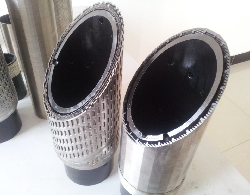
stainless steel wedge wire well screens research report
January 7, 2018Info Needed for Casing Design
• Mud weights
• Formation pressures
• Frack gradients
• Casing seats
• Casing sizes
• Directional plans
• Cement program
• Temperature profiles
• Base frack fluid, proppant type, and max proppant concentration
• Max anticipated frack surface pressure
• Produced fluid composition
Casing Specifications & Benefits
Casing can represent a big percentage of the overall well cost. This makes material grade, size, and connector selection not only an engineering consideration, but an economic one as well.
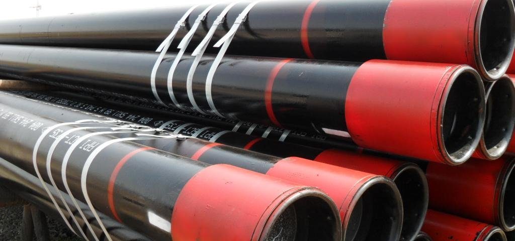
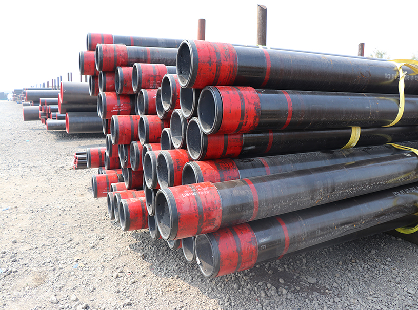
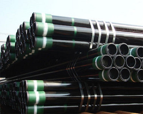
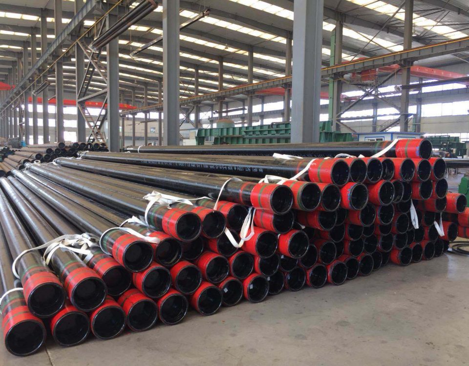
Casing pipe is available in large diameters that are designed aid the borehole in withstanding forces and chemically aggressive brines. It is typically made from carbon steel, which gets its strength through a heat treating process. Casing can also be specially fabricated using aluminum, stainless steel, titanium, and other materials. Once the casing is assembled and inserted into a freshly drilled section of a wellbore it must be held in place using cement.
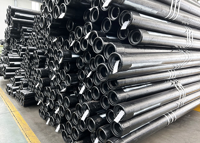
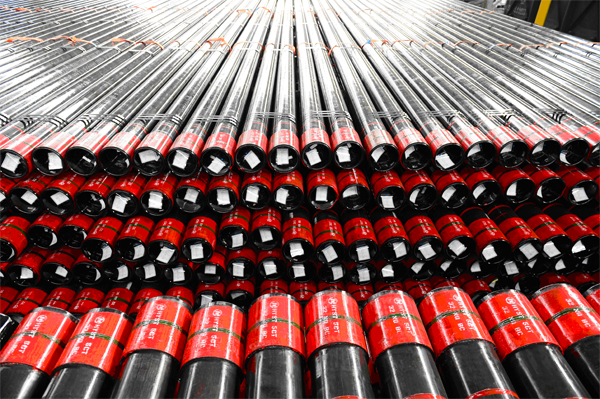
oil well casing and tubing pipe with L80 material EUE Thread
| Product Name | Brief Introduction | Material | Model Number | Brand Name | Minimum Order Quantity | Unit | Additional Description |
| 4 1/2″ oil casing | Casing and Tubing Standard: API 5CT, | Carbon Steel | 4 1/2″ | abter | 300 | Meter | Length: R2, R3.Application: serves as walls of a well .Packing: bundle or bulk |
| Material grade: J55, K55, N80, L80, T95, , | |||||||
| 5″ oil casing pipe | Casing and Tubing Standard: API 5CT, | Carbon Steel | 5″ | abter | 300 | Meter | Length: R2, R3.Application: serves as walls of a well .Packing: bundle or bulk |
| Material grade: J55, K55, N80, L80, T95, | |||||||
| 5 1/2″ casing pipe | Casing and Tubing Standard: API 5CT, | Carbon Steel | 5 1/2″ | abter | 300 | Meter | Length: R2, R3.Application: serves as walls of a well .Packing: bundle or bulk |
| Material grade: J55, K55, N80, L80, T95, | |||||||
| 6 5/8″ bushing pipe | Casing and Tubing Standard: API 5CT, | Carbon Steel | 6 5/8″ | abter | 300 | Meter | Length: R2, R3.Application: serves as walls of a well .Packing: bundle or bulk |
| Material grade: J55, K55, N80, L80, T95, | |||||||
| 7″ casing pipe | Casing and Tubing Standard: API 5CT, | Carbon Steel | 7″ | abter | 300 | Meter | Length: R2, R3.Application: serves as walls of a well .Packing: bundle or bulk |
| Material grade: J55, K55, N80, L80, T95, | |||||||
| 7 5/8″ oil casing pipe | Casing and Tubing Standard: API 5CT, | Carbon Steel | 7 5/8″ | abter | 300 | Meter | Length: R2, R3.Application: serves as walls of a well .Packing: bundle or bulk |
| Material grade: J55, K55, N80, L80, T95, | |||||||
| 8 5/8″oil casing | Casing and Tubing Standard: API 5CT, | Carbon Steel | 8 5/8″ | abter | 300 | Meter | Length: R2, R3.Application: serves as walls of a well .Packing: bundle or bulk |
| Material grade: J55, K55, N80, L80, T95, | |||||||
| 9 5/8″ oil casing | Casing and Tubing Standard: API 5CT, | Carbon Steel | 9 5/8″ | abter | 300 | Meter | Length: R2, R3.Application: serves as walls of a well .Packing: bundle or bulk |
| Material grade: J55, K55, N80, L80, T95, | |||||||
| 10 3/4″ casing | Casing and Tubing Standard: API 5CT, | Carbon Steel | 10 3/4″ | abter | 300 | Meter | Length: R2, R3.Application: serves as walls of a well .Packing: bundle or bulk |
| Material grade: J55, K55, N80, L80, T95, | |||||||
| 11 3/4″ oil pipe | Casing and Tubing Standard: API 5CT, | Carbon Steel | 11 3/4″ | abter | 300 | Meter | Length: R2, R3.Application: serves as walls of a well .Packing: bundle or bulk |
| Material grade: J55, K55, N80, L80, T95, | |||||||
| 13 3/8″oil casing | Casing and Tubing Standard: API 5CT, | Carbon Steel | 13 3/8″ | abter | 300 | Meter | Length: R2, R3.Application: serves as walls of a well .Packing: bundle or bulk |
| Material grade: J55, K55, N80, L80, T95, |
Load Cases
• Dividing the pipe rating by a corresponding load results in a design factor. If the design factor is greater than the minimum acceptable design factor, then the pipe is acceptable for use with that load.
DF
pipe rating =DF planned load
Devon Minimum Casing Design Factors
| Internal Yield (Burst) | 1.25 | (1.1 if SICP < 5,000 psi) |
| Collapse | 1.1 | |
| Tension | 1.4 | Based on yield strength |
| Compression | 1.2 | |
| Von Mises Triaxial | 1.25 |
Yield Strength vs Ultimate Strength
Tubing Leak
• This load case represents a high surface pressure on top of the completion fluid created by a tubing leak near the surface.
Surface pressure is based on a gas gradient extending upward from the reservoir. Tubing leaks are evaluated with both static and flowing temperature profiles.
Injection Down Casing
- This load case applies to wells that experience high pressure injection operations such as a fracing down casing. The load case models a surface pressure applied to a static fluid column. This is analogous to a screen-out during a frac job.
External Pressure Profile for Burst Cases
•The external pressure profile used for the standard burst load cases:
• Full mud gradient or deteriorated mud from the surface to the TOC.
• Cement mix-water gradient from the TOC to the outer casing shoe (typically 8.3 to 8.6 ppg).
• Pore pressure profile from the outer casing shoe to the base of the production casing.
External Casing Pressure
Production Casing Collapse Loads
• Full Evacuation
-This load case applies to severely depleted reservoirs or a large drawdown due to low permeability or plugged perforations.
-It assumes zero pressure on the inside of the pipe (such as fill over perfs and the well pressure blown down).
-The external pressure used is the mud gradient from surface to the casing bottom.
Internal Yield Strength
• Internal yield pressure is calculated from the Barlow Equation per API Bulletin 5C3
• P = 0.875 *[2*Yp*T]/D
• P= Internal yield pressure (psi)
• Yp = Yield strength of the pipe (example P110 is 110,000 psi)
• T = nominal wall thickness (inches)
• D = nominal OD of pipe (inches)
• Per API the calculated number is rounded to the nearest 10 psi.
• The 0.875 factor represents the allowable manufacturer’s tolerance of minus 12.5% on wall thickness per API specifications.
Internal Yield Strength Example Calculation
• 5.5” 23# P110 pipe has an ID of 4.67”
• wall thickness = [5.500 – 4.670] / 2 = 0.415 inches
• P = 0.875 * [2*Yp*T]/D
• P = 0.875 * [2 * 110,000 * 0.415] / 5.5 = 14,525 ~ 14,520 psi
• Internal yield strength per cement manual = 14,520 psi
Collapse Pressure Calculation
• Is based on four different equations based on the D/t ratio and the yield strength of the pipe
• Plastic collapse is based on a statistical regression analysis on empirical data from 2488 tests
• More information is in API Bulletin 5C3
Axial Strength (Pipe Body)
• Axial strength of pipe body is calculated from the formula below:
• Fy = (n/4) * (D2 – d2) Yp
• Fy = Tension strength (lbs. rounded to the nearest 1,000)
• Yp = Yield strength of pipe ( psi)
• D = OD of pipe (inches)
• d = ID of pipe (inches)
Joint Strength of Connection
• Calculations for joint strength of different API connections is found in API Bulletin 5C3.
• Joint strength of API connections is based on the ultimate strength and not the yield strength.
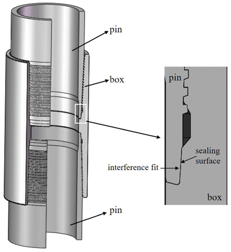
• Most (but not all) premium or proprietary connections are based on the yield strength of the connection.

