
Induction Bending Pipe for Piping Systems
May 26, 2025
Internally Lined Carbon Steel API 5L Pipelines
June 4, 2025
Pipe Spool Fabrication: A Detailed Scientific Analysis
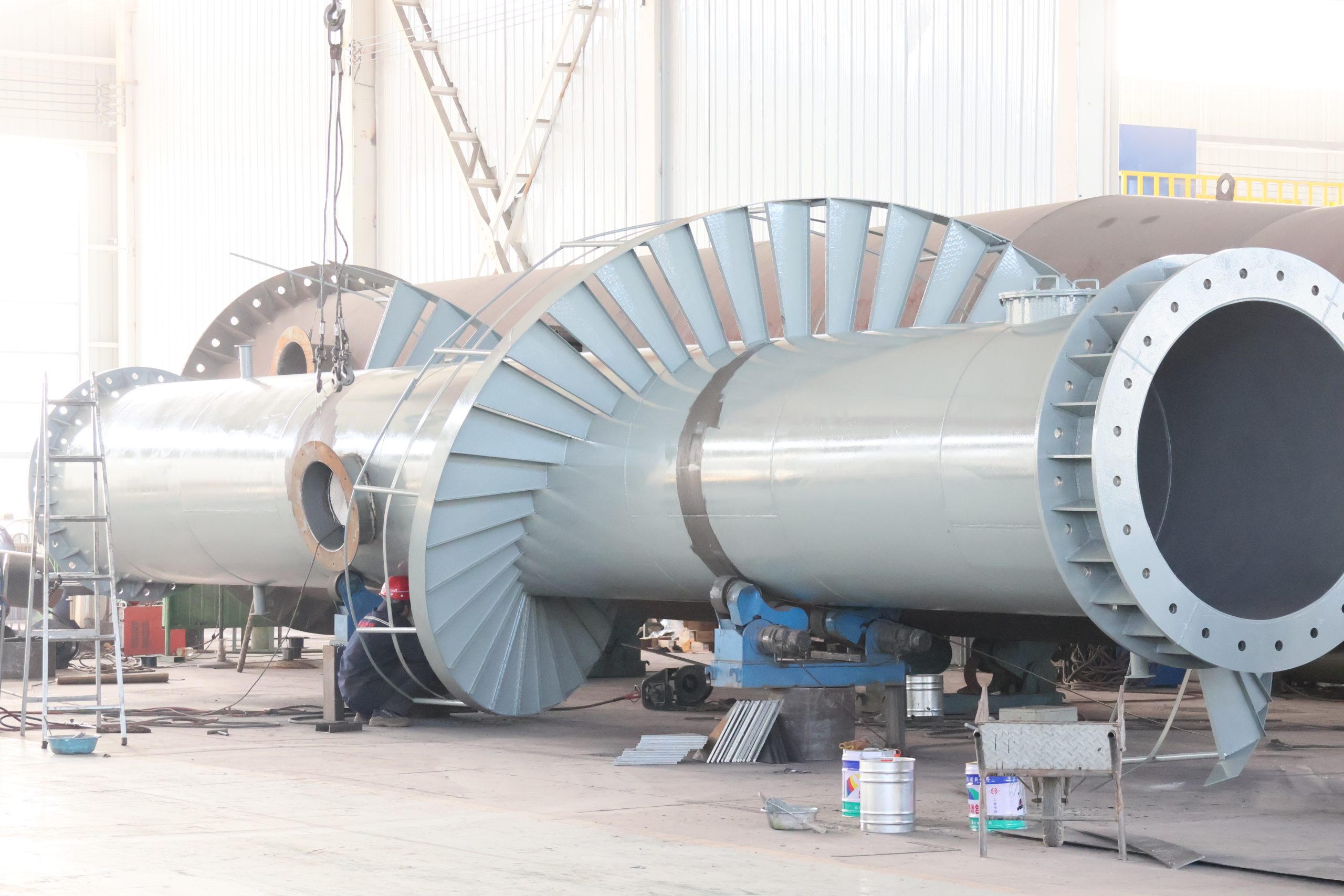
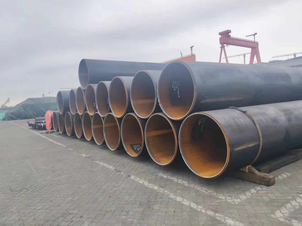
Pipe spool fabrication is a critical process in industries such as oil and gas, petrochemical, power generation, water treatment, and pharmaceuticals, where pre-assembled piping systems are required for efficient installation at construction sites. A pipe spool is a prefabricated section of a piping system, typically consisting of pipes, fittings (elbows, tees, reducers), flanges, valves, and other components, assembled in a controlled environment (workshop or factory) before being shipped to the site for installation. This method enhances efficiency, reduces on-site labor, and ensures high-quality standards through controlled fabrication processes.
This analysis will cover the following key areas:
- Overview of Pipe Spool Fabrication
- Key Parameters in Pipe Spool Fabrication (with Tables)
- Scientific and Technical Analysis of the Process
- Materials Selection and Their Impact
- Fabrication Techniques and Equipment
- Quality Control and Standards
- Optimization and Efficiency Considerations
- Case Studies and Practical Applications
- Conclusion
1. Overview of Pipe Spool Fabrication
Pipe spool fabrication involves the assembly of piping components into modular units that can be easily transported and installed. The process is widely used in industries requiring complex piping systems, as it minimizes field welding, reduces project timelines, and improves safety by limiting on-site work in hazardous environments. The fabrication process typically includes cutting, beveling, welding, fitting, inspection, and testing, all performed under controlled conditions.
Advantages of Pipe Spool Fabrication
- Improved Quality Control: Fabrication in a controlled environment ensures precision and adherence to standards.
- Cost Efficiency: Reduces on-site labor costs and minimizes errors during installation.
- Time Savings: Pre-fabrication allows parallel work streams, shortening project schedules.
- Safety: Limits on-site welding and handling of heavy components, reducing risks.
- Modularity: Facilitates easier transportation and installation of complex systems.
Challenges
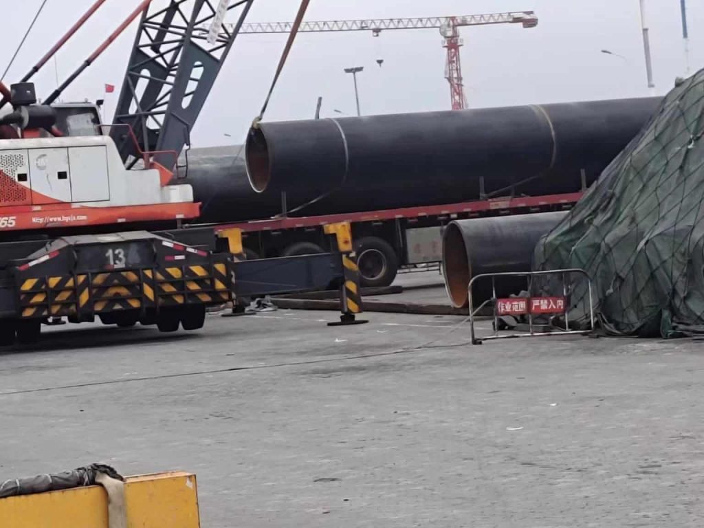
- Logistics: Transporting large spools requires careful planning to avoid damage.
- Material Compatibility: Ensuring all components are compatible with the process fluid and operating conditions.
- Dimensional Accuracy: Precise measurements are critical to avoid mismatches during field installation.
2. Key Parameters in Pipe Spool Fabrication
To ensure the success of pipe spool fabrication, several parameters must be carefully controlled. These parameters influence the quality, durability, and functionality of the final spool. Below is a detailed table summarizing the critical parameters, followed by explanations of their significance.
Table 1: Key Parameters in Pipe Spool Fabrication
| Parameter | Description | Typical Values/Standards | Impact on Fabrication |
|---|---|---|---|
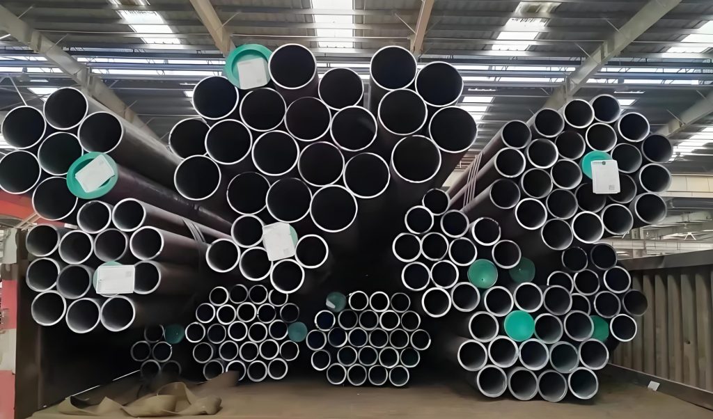
| Pipe Diameter | Nominal diameter of the pipe (NPS or DN) | 1/2” to 48” (NPS), DN15 to DN1200 | Determines spool size, weight, and welding requirements. |
| Wall Thickness | Thickness of the pipe wall (Schedule or mm) | Sch 10, 40, 80, 160; 2–50 mm | Affects pressure rating, welding difficulty, and material costs. |
| Material Type | Material of the pipe and components | Carbon steel, stainless steel, alloy steel, etc. | Impacts corrosion resistance, strength, and weldability. |
| Weld Imperfection Criteria | Acceptable limits for weld imperfections (e.g., porosity, cracks) | ASME B31.3, API 1104, ISO 5817 | Ensures structural integrity and compliance with standards. |
| Bevel Angle | Angle of pipe end preparation for welding | 30°–37.5° (typically 37.5° for V-groove) | Affects weld penetration and strength. |
| Welding Process | Type of welding used (e.g., GTAW, SMAW, GMAW) | TIG, MIG, Stick, Submerged Arc | Determines weld quality, speed, and cost. |
| Fit-Up Tolerance | Alignment accuracy of components before welding | ±1–2 mm (depending on standard) | Ensures proper joint alignment and minimizes stresses. |
| Hydrostatic Test Pressure | Pressure applied during testing to ensure integrity | 1.5x design pressure (ASME B31.3) | Verifies spool integrity under operating conditions. |
| Surface Finish | Surface treatment (e.g., pickling, passivation, coating) | Ra 0.8–3.2 µm (for stainless steel) | Impacts corrosion resistance and fluid flow characteristics. |
| Dimensional Tolerance | Allowable deviation in spool dimensions | ±3 mm for length, ±1.5 mm for alignment | Ensures compatibility with field installation. |
| Heat Treatment | Post-weld heat treatment (PWHT) requirements | 600–700°C for carbon steel (if required) | Reduces residual stresses and improves weld durability. |
| Non-Destructive Testing (NDT) | Methods to detect defects (e.g., RT, UT, PT, MT) | Radiography, Ultrasonic, Dye Penetrant, Magnetic Particle | Ensures weld and material integrity without damaging the spool. |
| Spool Weight | Total weight of the fabricated spool | 10 kg to several tons | Affects transportation and lifting requirements. |
Explanation of Key Parameters
- Pipe Diameter and Wall Thickness: Pipe diameter and wall thickness are critical for determining the spool’s capacity to handle pressure, flow rate, and structural loads. For example, Schedule 80 pipes have thicker walls than Schedule 40, making them suitable for higher-pressure applications but increasing material and fabrication costs.
- Scientific Consideration: The hoop stress (σ) in a pipe under pressure is calculated using the formula:
σ = (P · D) / (2t)
where
Pis the internal pressure,Dis the outer diameter, andtis the wall thickness. Selecting the appropriate thickness ensures the spool can withstand operational stresses without failure. - Material Type: Common materials include carbon steel (e.g., ASTM A106), stainless steel (e.g., 304/316), and alloy steels (e.g., P91 for high-temperature applications). Material selection depends on the process fluid, temperature, and corrosion environment.
- Scientific Consideration: Material properties such as yield strength, thermal expansion, and corrosion resistance must be analyzed. For instance, stainless steel is preferred in corrosive environments due to its high chromium content, which forms a passive oxide layer.
- Weld Imperfection Criteria: Weld imperfections (e.g., porosity, lack of fusion) are evaluated using standards like ASME B31.3 or ISO 5817. Imperfections must be within acceptable limits to ensure structural integrity.
- Scientific Consideration: Weld imperfections can act as stress concentrators, reducing the fatigue life of the spool. Non-destructive testing (NDT) methods like radiography and ultrasonic testing are used to detect subsurface defects.
- Bevel Angle and Fit-Up Tolerance: Proper beveling ensures adequate weld penetration, while tight fit-up tolerances reduce misalignment and residual stresses. Misaligned joints can lead to stress concentrations and premature failure.
- Scientific Consideration: The bevel angle affects the weld pool dynamics and heat-affected zone (HAZ). A 37.5° V-groove is standard for butt welds, balancing penetration and filler material use.
- Welding Process: Common welding processes include Gas Tungsten Arc Welding (GTAW/TIG) for high-precision welds, Gas Metal Arc Welding (GMAW/MIG) for faster production, and Shielded Metal Arc Welding (SMAW/Stick) for field repairs.
- Scientific Consideration: The choice of welding process affects the heat input, which influences the microstructure of the HAZ. For example, GTAW produces a smaller HAZ, reducing the risk of cracking in high-alloy materials.
- Hydrostatic Testing: Hydrostatic testing verifies the spool’s ability to withstand design pressure. The test pressure is typically 1.5 times the design pressure, as per ASME B31.3.
- Scientific Consideration: The test ensures no leaks or deformations occur under pressure, validating the integrity of welds and materials.
- Surface Finish and Heat Treatment: Surface finish is critical in industries like pharmaceuticals, where smooth surfaces (low Ra values) prevent bacterial growth. Post-weld heat treatment (PWHT) reduces residual stresses in welds, particularly for thick-walled or high-alloy spools.
- Scientific Consideration: PWHT alters the microstructure of the weld and HAZ, improving toughness and reducing the risk of stress corrosion cracking.
3. Scientific and Technical Analysis of the Process
Pipe spool fabrication is a multidisciplinary process that integrates materials science, mechanical engineering, and quality control. Below is a detailed analysis of the scientific principles and technical considerations involved.
3.1 Material Science Considerations
The selection of materials is driven by the operating conditions of the piping system, including temperature, pressure, and corrosivity of the fluid. Key material properties include:
- Yield Strength and Tensile Strength: Determines the pipe’s ability to withstand internal pressure and external loads.
- Thermal Conductivity and Expansion: Critical for high-temperature applications, where thermal expansion can cause misalignment or stress.
- Corrosion Resistance: Essential for fluids like seawater, acids, or hydrocarbons. For example, stainless steel 316L is used in marine environments due to its molybdenum content, which enhances pitting resistance.
Example Calculation
For a carbon steel pipe (ASTM A106 Gr. B) with a diameter of 12 inches (304.8 mm), wall thickness of 10 mm, and internal pressure of 50 bar (5 MPa), the hoop stress is:
The yield strength of A106 Gr. B is approximately 240 MPa, providing a safety factor of:
This indicates the pipe is suitable for the application, as a safety factor > 2 is typically required.
3.2 Welding Science
Welding is the backbone of pipe spool fabrication, and its quality directly affects the spool’s performance. Key scientific considerations include:
- Heat Input: Excessive heat input can cause grain growth in the HAZ, reducing toughness. Heat input (Q) is calculated as:
Q = (Voltage · Current · 60) / Welding Speed (mm/min)
- Weld Imperfections: Porosity, inclusions, and cracks can compromise the weld’s integrity. These are minimized through proper shielding gas selection, electrode choice, and welder skill.
- Residual Stresses: Welding induces residual stresses due to thermal expansion and contraction. PWHT or controlled cooling can mitigate these stresses.
3.3 Fluid Dynamics and Pipe Design
The internal flow characteristics of the spool affect its performance in service. Key considerations include:
- Pressure Drop: Determined by pipe diameter, length, and surface roughness. The Darcy-Weisbach equation is used to calculate pressure drop:
ΔP = f · (L / D) · (ρ V² / 2)
where
fis the friction factor,Lis the pipe length,Dis the diameter,ρis the fluid density, andVis the velocity. - Flow Regime: Laminar or turbulent flow affects pressure drop and erosion rates. For high-velocity fluids, smoother surfaces (e.g., electropolished stainless steel) are preferred to reduce turbulence.
3.4 Structural Integrity
The spool must withstand internal pressure, external loads (e.g., wind, seismic), and thermal expansion. Finite Element Analysis (FEA) is often used to simulate stresses and ensure the spool meets design requirements. For example, ASME B31.3 provides guidelines for calculating allowable stresses based on material properties and operating conditions.
4. Materials Selection and Their Impact
Material selection is a critical aspect of pipe spool fabrication, as it affects cost, durability, and performance. Below is a table summarizing common materials and their applications.
Table 2: Common Materials for Pipe Spool Fabrication
| Material | Standard | Applications | Advantages | Limitations |
|---|---|---|---|---|
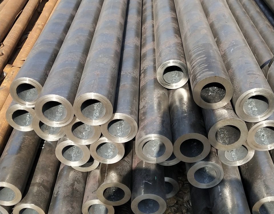
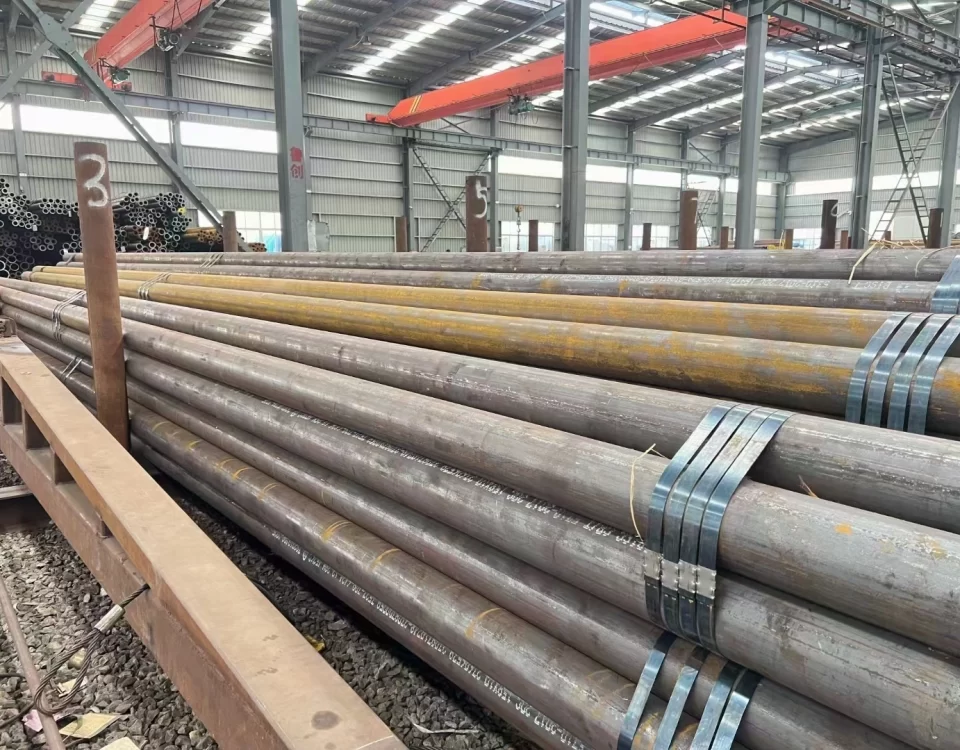
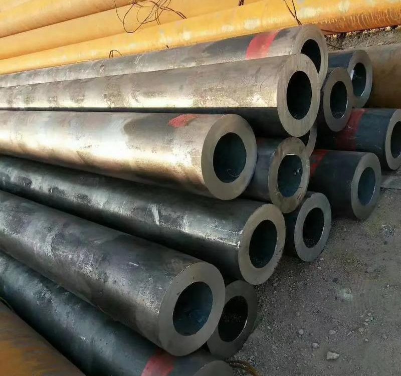
| Carbon Steel (A106 Gr. B) | ASTM A106 | Oil and gas, water, steam | Cost-effective, high strength | Susceptible to corrosion |
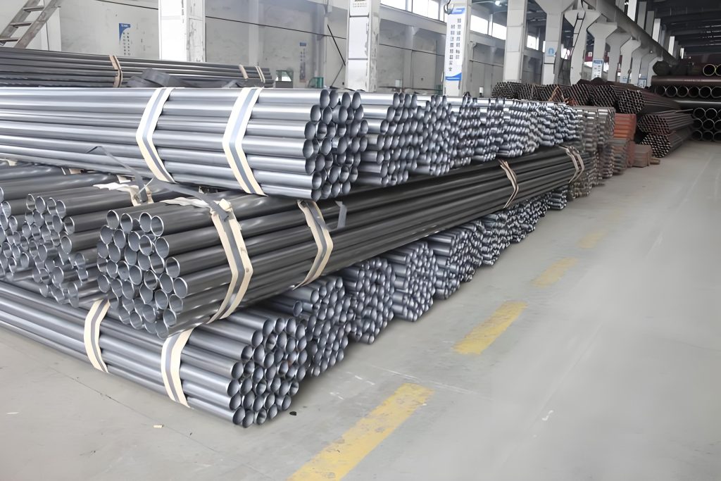
| Stainless Steel (304/316) | ASTM A312 | Chemical, pharmaceutical, marine | Corrosion-resistant, durable | Higher cost, lower strength than carbon steel |
| Alloy Steel (P91, P22) | ASTM A335 | High-temperature power plants | High-temperature strength, creep resistance | Expensive, requires PWHT |
| Duplex Stainless Steel | ASTM A790 | Offshore oil and gas, corrosive environments | High strength, excellent corrosion resistance | Complex welding, high cost |
| PVC/CPVC | ASTM D1785 | Water treatment, low-pressure systems | Lightweight, corrosion-resistant | Limited to low temperatures and pressures |
Scientific Considerations
- Corrosion: The corrosion rate depends on the fluid chemistry and material properties. For example, stainless steel 316L has a corrosion rate of <0.1 mm/year in seawater, compared to >1 mm/year for carbon steel.
- Thermal Expansion: Materials like stainless steel have higher thermal expansion coefficients (e.g., 16 µm/m·K for 316 SS vs. 12 µm/m·K for carbon steel), requiring expansion joints or flexible supports in high-temperature systems.
- Weldability: High-alloy materials like duplex stainless steel require precise control of welding parameters to avoid phase imbalances (e.g., ferrite-austenite ratio).
5. Fabrication Techniques and Equipment
The fabrication process involves several steps, each requiring specialized equipment and techniques. Below is an overview of the key stages and tools.
5.1 Cutting and Beveling
- Process: Pipes are cut to length and beveled to prepare for welding. Common methods include plasma cutting, oxy-fuel cutting, and mechanical cutting.
- Equipment: CNC pipe cutting machines, beveling machines.
- Scientific Consideration: Precise cutting ensures dimensional accuracy, while proper beveling facilitates weld penetration. For example, a 37.5° bevel angle is standard for V-groove welds to balance penetration and filler material use.
5.2 Welding
- Process: Components are joined using welding processes like GTAW, GMAW, or SMAW. Automated welding systems are increasingly used for consistency.
- Equipment: Orbital welding machines, TIG/MIG welders, welding positioners.
- Scientific Consideration: Weld quality depends on parameters like current, voltage, and travel speed. For example, GTAW with low heat input is preferred for stainless steel to minimize distortion.
5.3 Assembly and Fit-Up
- Process: Components are aligned and clamped before welding to ensure proper fit-up.
- Equipment: Pipe alignment clamps, jigs, and fixtures.
- Scientific Consideration: Misalignment can induce residual stresses, reducing fatigue life. Tolerances of ±1–2 mm are typically required.
5.4 Inspection and Testing
- Process: Non-destructive testing (NDT) methods like radiography (RT), ultrasonic testing (UT), and dye penetrant testing (PT) are used to verify weld quality. Hydrostatic or pneumatic testing ensures leak-tightness.
- Equipment: X-ray machines, ultrasonic flaw detectors, pressure testing rigs.
- Scientific Consideration: NDT methods detect defects like cracks or porosity, which can act as stress concentrators. Hydrostatic testing validates the spool’s ability to withstand design pressure.
6. Quality Control and Standards
Quality control is paramount in pipe spool fabrication to ensure compliance with industry standards and project specifications. Key standards include:
- ASME B31.3: Process Piping, governing design, fabrication, and testing.
- API 1104: Welding of pipelines and related facilities.
- ISO 5817: Quality levels for weld imperfections.
- ASTM Standards: Material specifications (e.g., A106, A312).
Quality Control Measures
- Material Inspection: Verify material certificates and perform chemical analysis to ensure compliance with specifications.
- Weld Imperfection Evaluation: Use NDT to detect defects and ensure welds meet acceptance criteria.
- Dimensional Checks: Measure spool dimensions to ensure compliance with tolerances.
- Pressure Testing: Conduct hydrostatic or pneumatic tests to verify integrity.
- Documentation: Maintain records of material certificates, weld maps, and test reports for traceability.
Scientific Consideration: Statistical process control (SPC) can be used to monitor fabrication quality. For example, control charts can track weld imperfection rates, ensuring they remain within acceptable limits.
7. Optimization and Efficiency Considerations
To maximize the efficiency of pipe spool fabrication, several strategies can be employed:
- Automation: Use CNC cutting machines and automated welding systems to improve precision and reduce labor costs.
- Lean Manufacturing: Implement lean principles to minimize waste, such as optimizing material use and reducing rework.
- Modular Design: Design spools to minimize field welds, reducing on-site labor and costs.
- Digital Tools: Use Building Information Modeling (BIM) and 3D CAD software to plan and visualize spool designs, ensuring compatibility with field conditions.
- Supply Chain Management: Ensure timely delivery of materials to avoid production delays.
Scientific Consideration: Optimization can be modeled using operations research techniques, such as linear programming, to minimize costs while meeting project constraints. For example, the objective function could minimize total fabrication cost:
where Cm is material cost, Cl is labor cost, and Ct is transportation cost, subject to constraints like delivery deadlines and quality standards.
8. Case Studies and Practical Applications
Case Study 1: Oil and Gas Refinery
A refinery project required 500 pipe spools for a crude oil processing unit. The spools were fabricated using carbon steel (A106 Gr. B) with diameters ranging from 4” to 24” and Schedule 40–80 wall thicknesses. Key challenges included:
- Corrosion: The crude oil contained sulfur compounds, requiring internal coatings.
- Tight Tolerances: Spools had to align with existing equipment, requiring ±1 mm dimensional accuracy.
- Schedule: The project timeline required parallel fabrication of multiple spools.
Solution
- Used automated GTAW welding to ensure high-quality welds.
- Implemented radiographic testing (RT) for all critical welds.
- Employed BIM to coordinate spool designs with field conditions.
Outcome
The project was completed on time, with zero leaks during hydrostatic testing and full compliance with ASME B31.3.
Case Study 2: Pharmaceutical Plant
A pharmaceutical plant required stainless steel (316L) spools for a sterile water system. Key requirements included:
-
- Surface Finish: Ra < 0.8 µm to prevent bacterial growth.
- Cleanliness: No contamination during fabrication.
- Weld Quality: 100% radiographic inspection for welds.
Solution
- Used orbital GTAW welding for consistent, high-quality welds.
- Performed electropolishing to achieve the required surface finish.
- Conducted passivation to enhance corrosion resistance.
Outcome
The spools met stringent FDA requirements, ensuring compliance with Good Manufacturing Practices (GMP).
Pipe spool fabrication is a complex, multidisciplinary process that requires careful consideration of materials, welding techniques, quality control, and optimization strategies. By adhering to industry standards like ASME B31.3 and employing advanced fabrication techniques, manufacturers can produce high-quality spools that meet the demands of industries such as oil and gas, petrochemical, and pharmaceuticals. The key parameters outlined in the tables—pipe diameter, wall thickness, material type, weld quality, and testing requirements—form the backbone of the fabrication process, ensuring structural integrity and operational reliability.
Primary Keywords:
Pipe spool fabrication
Piping spool manufacturing
Prefabricated piping systems
Pipe spool assembly
Industrial pipe fabrication
Technical Keywords:
Pipe welding techniques
Non-destructive testing (NDT) for piping
Hydrostatic testing for pipe spools
ASME B31.3 compliance
Weld imperfection standards
Material-Related Keywords:
Carbon steel pipe spools
Stainless steel piping fabrication
Alloy steel pipe spools
Duplex stainless steel piping
PVC pipe spool manufacturing
Industry-Specific Keywords:
Oil and gas piping fabrication
Petrochemical pipe spools
Pharmaceutical piping systems
Power plant pipe fabrication
Water treatment piping solutions
Process and Equipment Keywords:
CNC pipe cutting
Orbital welding for pipe spools
Related posts
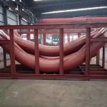
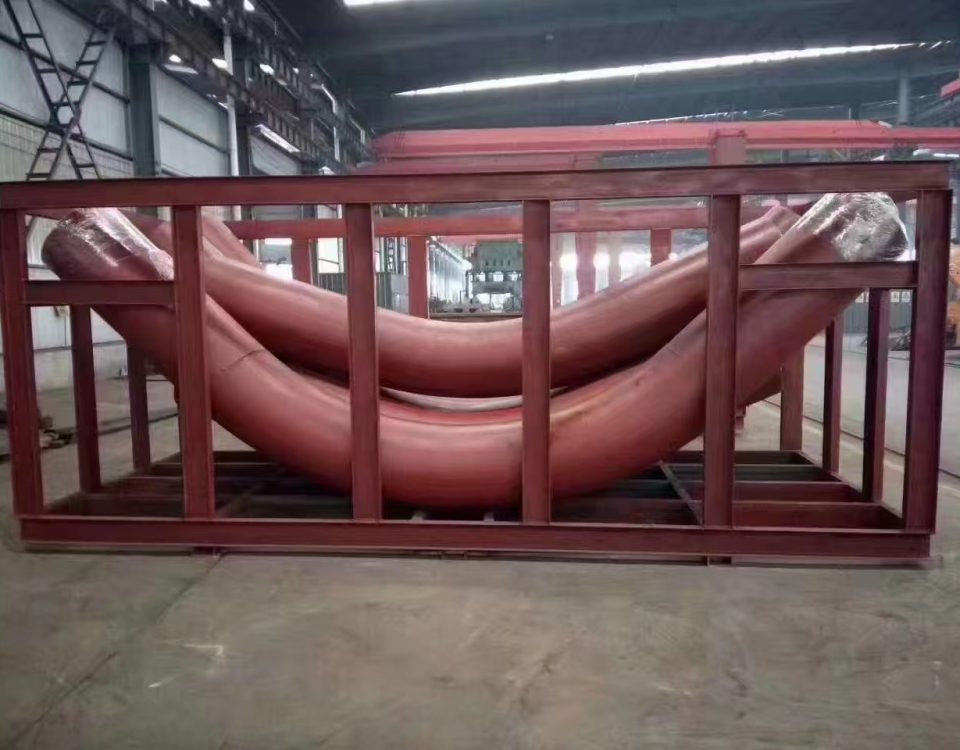
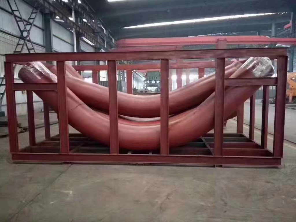
Induction bends come in standard bend angles (e.g. 45°, 90°, etc.) or can be custom made to specific bend angles. Compound bends (out-of-plane) bends in a single joint of pipe can also be produced. The bend radius is specified as a function of the diameter. For example, common bend radii for induction bends are 3D, 5D and 7D, where D is the nominal pipe diameter.