
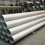
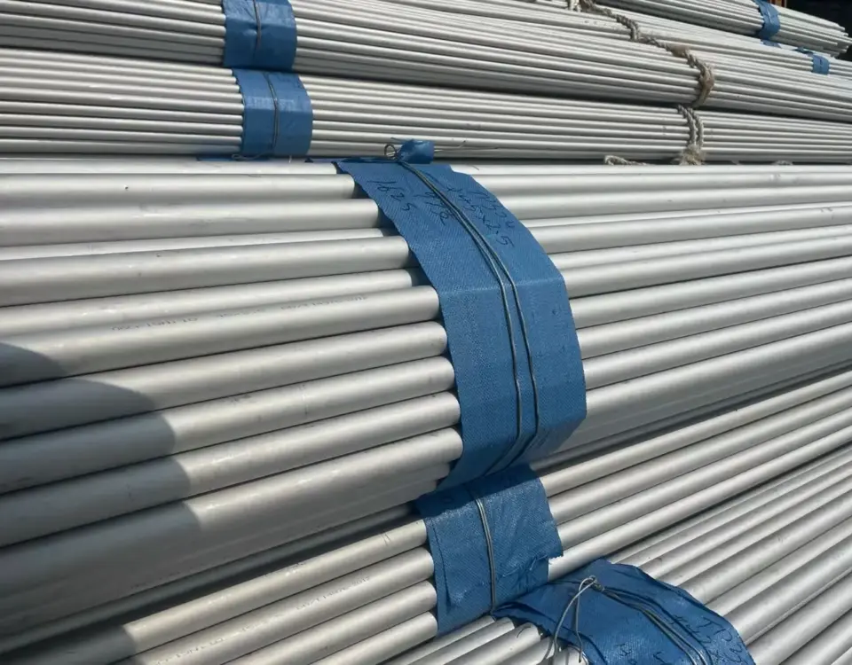
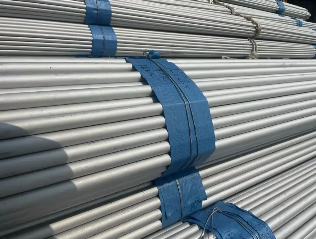
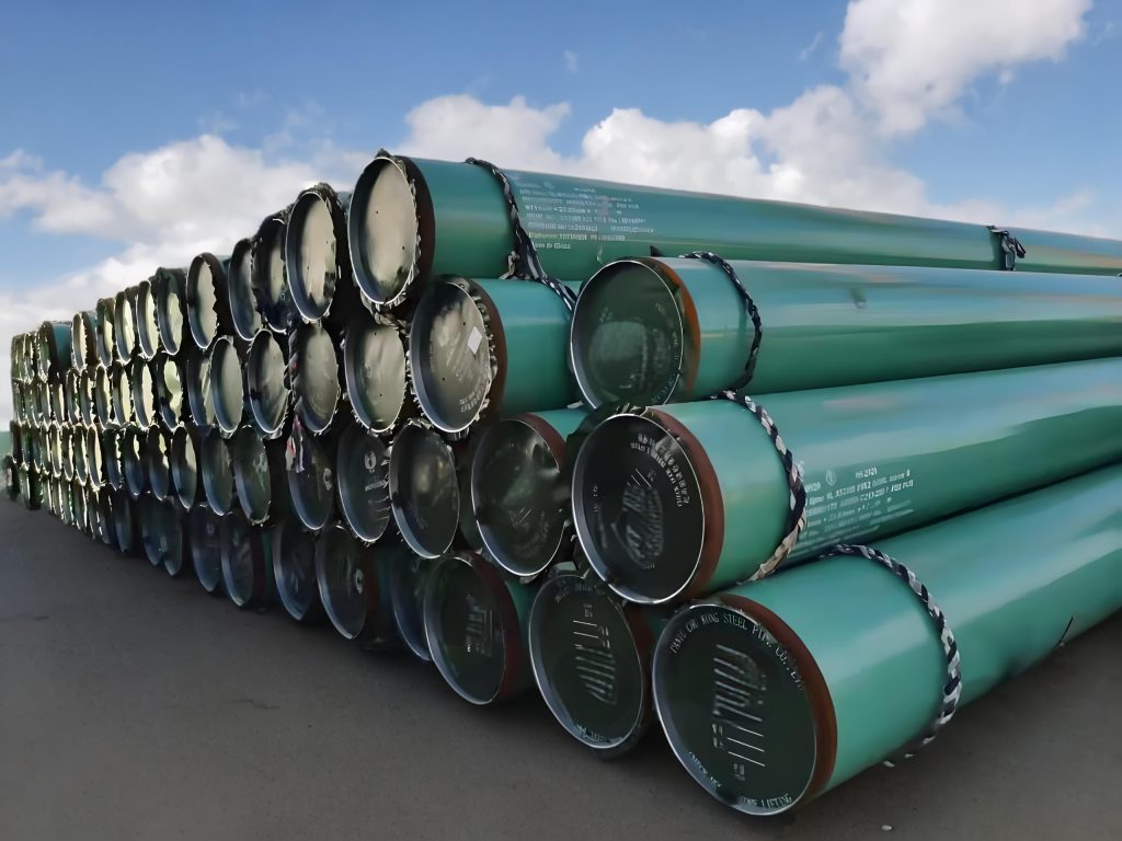
25Cr-20Ni Alloy Heat-Resistant Stainless Steel Pipe (310S)
May 23, 2025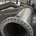
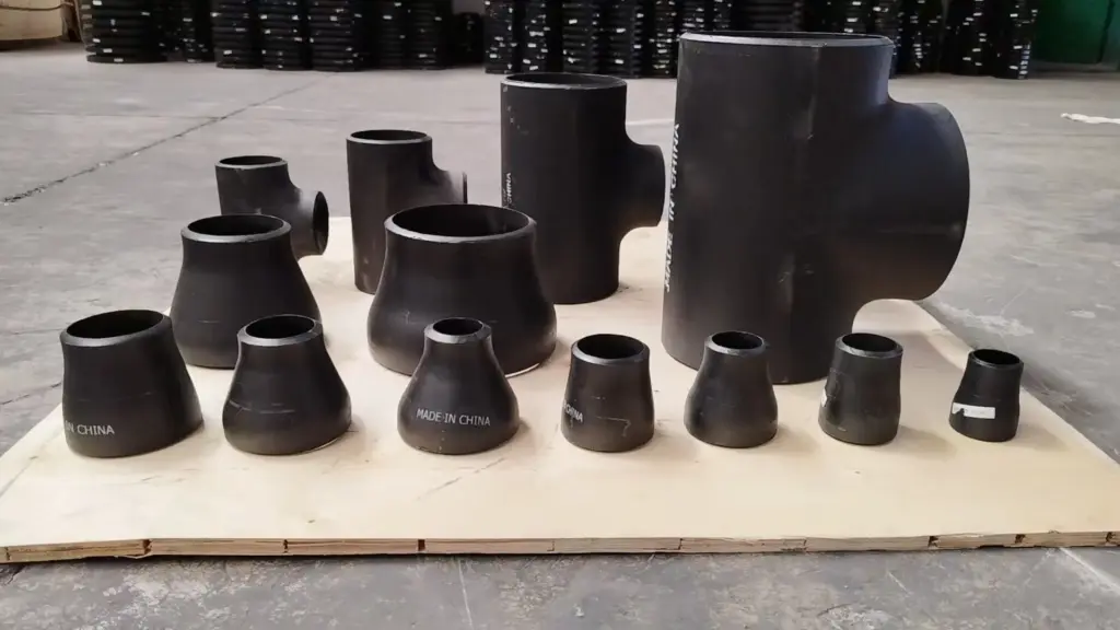
Pipe Spool Fabrication | Piping spool manufacturing| Prefabricated piping systems
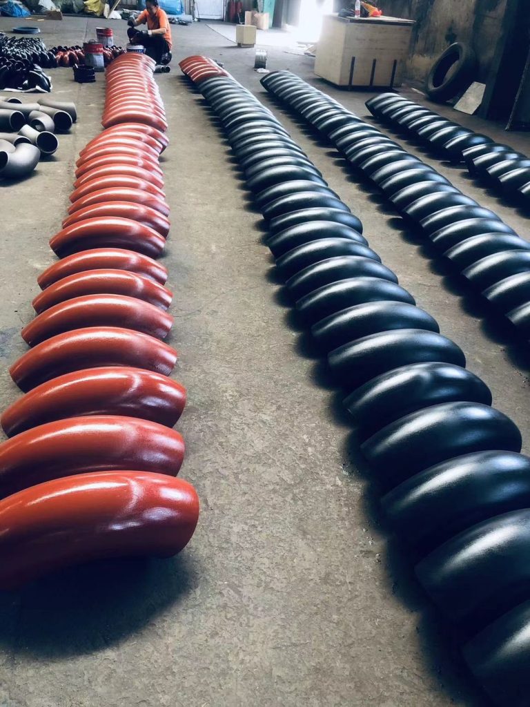
May 31, 2025Induction Bending Pipe for Piping Systems
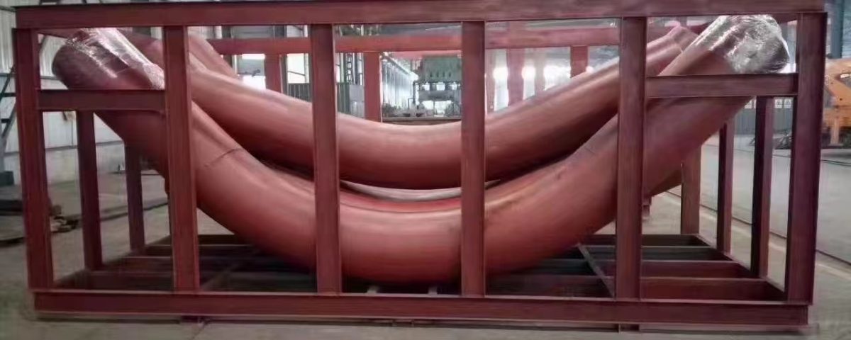
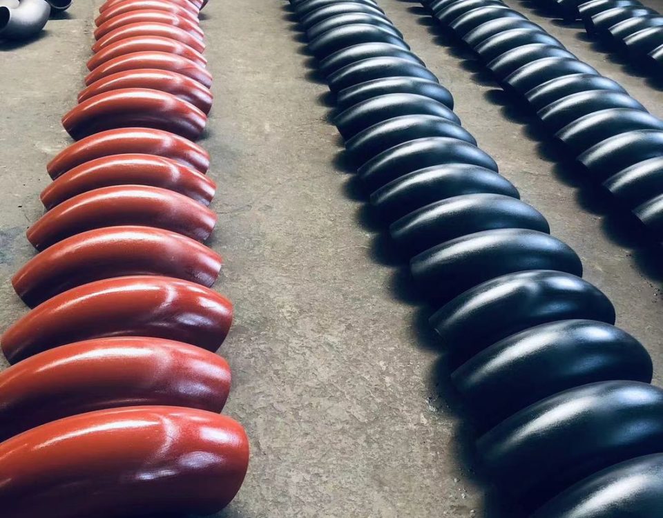
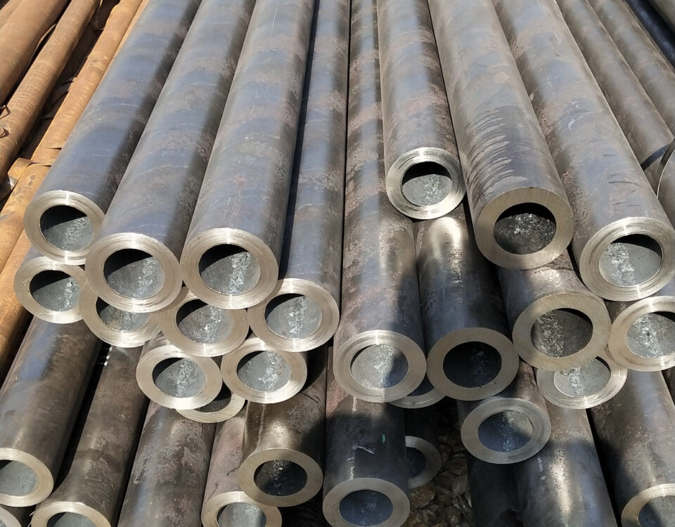
Induction bends come in standard bend angles (e.g. 45°, 90°, etc.) or can be custom made to specific bend angles. Compound bends (out-of-plane) bends in a single joint of pipe can also be produced. The bend radius is specified as a function of the diameter. For example, common bend radii for induction bends are 3D, 5D and 7D, where D is the nominal pipe diameter.
Induction Bending Pipe for Piping Systems
Introduction
Induction bending is a sophisticated and highly controlled pipe bending process that has become a cornerstone in modern piping systems across industries such as oil and gas, petrochemical, power generation, and infrastructure. This technology allows for the precise formation of pipe bends with varying radii, including 3D, 5D, and 7D configurations, while maintaining the structural integrity and mechanical properties of the material. Our company is a leading manufacturer of induction bending pipes, adhering to stringent standards such as ASME B16.49, and we pride ourselves on delivering high-quality, reliable solutions tailored to the needs of our clients.
This article provides an in-depth exploration of induction bending pipes, including the scientific principles behind the process, the advantages of induction bends, the manufacturing process under ASME B16.49, the specific benefits of 3D, 5D, and 7D bends, our cutting-edge equipment, integrated inspection services, and the comprehensive induction bending-related services we offer. By combining technical analysis with practical insights, we aim to showcase why induction bending is a preferred choice for modern piping systems and how our company leads the industry in this domain.
The Science of Induction Bending
Principles of Induction Bending
Induction bending is a hot-forming process that utilizes localized heating and controlled mechanical force to shape pipes into precise bends. The process involves the following key steps:
- Localized Heating: An induction coil, powered by high-frequency electrical current, is placed around a specific section of the pipe. This coil generates an electromagnetic field that induces eddy currents within the pipe, heating a narrow circumferential band to temperatures typically between 850°C and 1100°C, depending on the material (e.g., carbon steel, stainless steel, or alloy steel).
- Controlled Bending: Once the desired temperature is reached, the pipe is slowly pushed through the induction coil while a bending arm applies a controlled force to form the bend. The heated section becomes malleable, allowing it to deform without cracking or compromising the pipe’s integrity.
- Cooling: Immediately after bending, the heated section is cooled using a water spray or air to stabilize the newly formed shape and prevent distortion. This rapid cooling also influences the metallurgical structure of the material, often requiring post-bend heat treatment to restore desired mechanical properties.
Metallurgical and Mechanical Considerations
The induction bending process induces thermal and mechanical stresses in the pipe, which must be carefully managed to maintain material properties. Key metallurgical and mechanical aspects include:
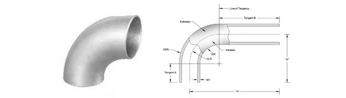
- Wall Thinning and Thickening: During bending, the outer radius (extrados) of the pipe experiences wall thinning due to tensile stresses, while the inner radius (intrados) undergoes wall thickening due to compressive stresses. ASME B16.49 specifies that the minimum wall thickness at the extrados must meet design pressure requirements, typically not less than the minimum required for straight pipe.
- Ovality Control: Ovality, or the deviation from a perfect circular cross-section, is a critical parameter in induction bending. ASME B16.49 and ISO 15590-1 mandate that ovality should not exceed 3% of the nominal diameter in the bend body and 1% in the tangent portions. Precise control of bending parameters ensures compliance with these tolerances.
- Microstructural Changes: The high temperatures involved in induction bending can alter the microstructure of the pipe material, potentially affecting its strength and toughness. Post-bend heat treatments, such as normalizing, quenching, and tempering, are often applied to restore or enhance the material’s properties. For example, carbon steel bends may be normalized by heating above the transformation temperature and cooling in still air to achieve a uniform microstructure.
Material Compatibility
Induction bending is versatile and compatible with a wide range of materials, including:
- Carbon steels (e.g., API 5L Gr. B, ASTM A106 Gr. B)
- High-yield steels (e.g., API 5L X42 to X80)
- Stainless steels (e.g., ASTM A312 304L, 316L)
- Alloy steels (e.g., ASTM A335 P11, P22, P91)
- Nickel alloys (e.g., Inconel, Monel, Hastelloy)
- Duplex and super-duplex stainless steels
- Titanium and copper-nickel alloys
This versatility makes induction bending suitable for diverse applications, from corrosive environments in petrochemical plants to high-pressure pipelines in oil and gas transmission.
Manufacture of ASME B16.49 Induction Bends
Overview of ASME B16.49
ASME B16.49 is the standard specification for factory-made, wrought steel, butt-welding induction bends used in transportation and distribution piping systems, such as those governed by ASME B31.4 (liquid transportation), B31.8 (gas transmission), and B31.11 (slurry transportation). The standard outlines requirements for design, material selection, manufacturing, testing, marking, and inspection to ensure the reliability and safety of induction bends.
Manufacturing Process
Our company adheres strictly to ASME B16.49 in the production of induction bends, ensuring compliance with all specified requirements. The manufacturing process involves the following stages:
- Material Selection: Pipes are selected based on client specifications, typically seamless or welded carbon steel, stainless steel, or alloy steel. The chemical composition is controlled to ensure a carbon equivalent (C.E.) not exceeding 0.45% to minimize weldability issues.
- Induction Bending: The pipe is placed in a mid-frequency induction bending machine, where the induction coil heats a narrow band of the pipe. The bending radius (e.g., 3D, 5D, 7D) is determined by the centerline radius (R) relative to the nominal pipe diameter (D). For example, a 6-inch 5D bend has a centerline radius of R = 5 × 6” = 30” (762 mm).
- Post-Bend Heat Treatment: After bending, the pipe undergoes heat treatment to relieve residual stresses and restore mechanical properties. Common methods include:
- Stress Relieving or Tempering: Heating to 480°C–675°C for at least 30 minutes per 25 mm of thickness.
- Normalizing: Heating above the transformation temperature and cooling in still air.
- Quenching and Tempering: Heating above the transformation temperature, quenching in water or oil, and tempering to achieve desired hardness and toughness.
- Weld End Preparation: The ends of the bend are beveled in accordance with ASME B16.25 to ensure compatibility with butt-welding in piping systems.
- Testing and Inspection: Each bend undergoes rigorous testing to verify compliance with ASME B16.49, including:
- Dimensional Inspection: Verifying bend angle, radius, ovality, and tangent lengths.
- Visual Examination: Checking for surface defects such as cracks or laminations.
- Mechanical Testing: Conducting tensile tests, Charpy V-notch tests, and hardness tests.
- Non-Destructive Testing (NDT): Performing ultrasonic testing (UT) and radiographic testing (RT) to detect internal defects.
- Marking and Documentation: Each bend is marked with details such as material grade, bend radius, angle, and heat treatment status. A Manufacturer’s Data Report (MDR) is provided to document compliance with ASME B16.49.
3D, 5D, and 7D Bends
Induction bends are classified based on their centerline radius relative to the nominal pipe diameter (D). The most common configurations are:
- 3D Bends: The centerline radius is three times the nominal diameter (R = 3D). For a 6-inch pipe, R = 18 inches (457.2 mm). These bends are used in applications requiring tighter turns, such as in compact piping layouts.
- 5D Bends: The centerline radius is five times the nominal diameter (R = 5D). For a 6-inch pipe, R = 30 inches (762 mm). These bends offer smoother flow and reduced pressure loss, making them ideal for long-distance pipelines.
- 7D Bends: The centerline radius is seven times the nominal diameter (R = 7D). For a 6-inch pipe, R = 42 inches (1066.8 mm). These bends are used in applications requiring minimal flow resistance, such as high-pressure gas transmission lines.
Each bend type is selected based on the specific requirements of the piping system, including flow characteristics, space constraints, and pressure ratings.
Dimensions Of Buttweld Long Radius 3d/5d Bend
| Nominal Pipe Size |
Outside Diameter |
Inside Diameter |
Wall Thickness |
Center To End |
Pipe Schedule |
Weight Pounds |
| 1/2 | 0.84 | 0.622 | 0.109 | 1.5 | 40 | 0.16 |
| 3/4 | 1.05 | 0.824 | 0.113 | 1.5 | 40 | 0.17 |
| 1 | 1.32 | 1.049 | 0.133 | 1.5 | 40 | 0.4 |
| 1 1/4 | 1.66 | 1.38 | 0.14 | 1.88 | 40 | 0.55 |
| 1 1/2 | 1.9 | 1.61 | 0.145 | 2.25 | 40 | 0.8 |
| 2 | 2.38 | 2.07 | 0.154 | 3 | 40 | 1.6 |
| 2 1/2 | 2.88 | 2.47 | 0.203 | 3.75 | 40 | 3.2 |
| 3 | 3.5 | 3.07 | 0.216 | 4.5 | 40 | 4.8 |
| 3 1/2 | 4 | 3.55 | 0.226 | 5.25 | 40 | 6.6 |
| 4 | 4.5 | 4.03 | 0.237 | 6 | 40 | 8.9 |
| 5 | 5.56 | 5.05 | 0.258 | 7.5 | 40 | 15.1 |
| 6 | 6.62 | 6.07 | 0.28 | 9 | 40 | 24 |
| 8 | 8.62 | 7.98 | 0.322 | 12 | 40 | 47.8 |
| 10 | 10.75 | 10.02 | 0.365 | 15 | 40 | 83.4 |
| 12 | 12.75 | 12 | 0.375 | 18 | * | 123 |
| 14 | 14 | 13.25 | 0.375 | 21 | 30 | 155 |
| 16 | 16 | 15.25 | 0.375 | 24 | 30 | 206 |
| 18 | 18 | 17.25 | 0.375 | 27 | * | 262 |
| 20 | 20 | 19.25 | 0.375 | 30 | 20 | 324 |
| 24 | 24 | 23.25 | 0.375 | 36 | 20 | 466 |
| 30 | 30 | 29.25 | 0.375 | 45 | * | 720 |
| 36 | 36 | 35.25 | 0.375 | 54 | * | 1,039 |
| 42 | 42 | 41.25 | 0.375 | 63 | * | 1,420 |
| 48 | 48 | 47.25 | 0.375 | 72 | * | 2,000 |
Benefits of Induction Bends
Induction bends offer numerous advantages over traditional pipe bending methods (e.g., cold bending or welded elbows), making them a preferred choice for critical piping systems. Below are the key benefits:
- Enhanced Flow Characteristics: Large-radius bends (e.g., 5D, 7D) reduce turbulence and pressure loss compared to standard elbows, improving the efficiency of fluid or gas transport. This is particularly important in long-distance pipelines where energy costs are a significant consideration.
- Reduced Welds: Induction bends eliminate the need for multiple welded elbows, reducing the number of welds in the system. Fewer welds translate to lower fabrication costs, reduced inspection requirements, and improved system integrity, as welds are potential points of failure.
- Cost Efficiency: Straight pipe material is generally less expensive than pre-fabricated elbows, and induction bending allows for rapid production of bends without the need for internal mandrels or sand filling. This reduces production time and costs compared to fire bending or weld fabrication.
- Flexibility in Design: Induction bends can be produced with custom angles (e.g., 30°, 60°, 90°) and radii (e.g., 3D to 10D), offering greater flexibility in piping design. Compound bends (out-of-plane bends) can also be created in a single pipe joint, accommodating complex routing requirements.
- Superior Material Integrity: The controlled heating and cooling process minimizes defects such as cracks or buckles, ensuring the bend retains the mechanical properties of the parent pipe. Post-bend heat treatment further enhances material performance, making induction bends suitable for high-pressure and high-temperature applications.
- Versatility Across Industries: Induction bends are used in diverse applications, including:
- Oil and Gas: For pipelines transporting crude oil, natural gas, or refined products.
- Petrochemical: For process piping in refineries and chemical plants.
- Power Generation: For steam and cooling water systems in power plants.
- Infrastructure: For water supply and wastewater systems.
- Environmental Benefits: By reducing the need for welds and minimizing material waste, induction bending is a more sustainable option compared to traditional fabrication methods. Additionally, the energy-efficient nature of induction heating lowers the carbon footprint of the manufacturing process.
Our Induction Bending-Related Services
As a leading manufacturer of induction bending pipes, our company offers a comprehensive suite of services to meet the diverse needs of our clients. These services are designed to deliver high-quality, customized solutions while ensuring compliance with industry standards.
- Custom Bend Design and Engineering: Our team of experienced engineers collaborates with clients to design induction bends tailored to specific project requirements. We provide:
- Bend Radius and Angle Customization: Producing bends with radii from 2.5D to 10D and angles from 1° to 180°.
- Material Selection Guidance: Recommending materials based on operating conditions, such as corrosion resistance or high-temperature performance.
- Finite Element Analysis (FEA): Simulating stress and deformation to optimize bend design and ensure structural integrity.
- Manufacturing and Fabrication: Our state-of-the-art manufacturing facility is equipped to produce induction bends in a wide range of sizes (1/2” to 38” outer diameter) and wall thicknesses (SCH 5 to XXS). We offer:
- Seamless and Welded Bends: Catering to both seamless and welded pipe requirements.
- Tangent Length Options: Providing bends with or without tangent lengths for easy field welding.
- Specialty Bends: Producing compound bends and multi-plane bends for complex piping layouts.
- Post-Bend Heat Treatment: We offer a range of heat treatment options to meet ASME B16.49 requirements, including stress relieving, normalizing, and quenching and tempering. Our heat treatment processes are precisely controlled to ensure consistent material properties across all bends.
- Testing and Inspection: Our integrated inspection services, detailed below, ensure that every bend meets the highest quality standards. We perform dimensional checks, mechanical testing, and NDT to verify compliance with ASME B16.49 and client specifications.
- Coating and Finishing: To enhance durability and corrosion resistance, we provide value-added services such as:
- Hot-dip galvanizing
- Epoxy and FBE (fusion-bonded epoxy) coating
- Sandblasting and electro-polishing
Scientific Analysis
The advantages of induction bending pipes are grounded in both engineering and material science principles. The process ensures minimal distortion and maintains the structural integrity of the pipe through controlled heating and cooling cycles. Finite Element Analysis (FEA) is often used to simulate the bending process, predicting stress distribution, wall thinning, and ovality. This scientific approach allows for precise control over the bending parameters, ensuring compliance with standards like ASME B16.49.
From a fluid dynamics perspective, larger radius bends (e.g., 5D and 7D) reduce turbulence and pressure drop, as described by the Darcy-Weisbach equation for frictional losses in pipes:
Where:
- \(h_f\): Head loss due to friction
- \(f\): Friction factor
- \(L\): Pipe length
- \(D\): Pipe diameter
- \(v\): Fluid velocity
- \(g\): Gravitational acceleration
Larger radius bends decrease the effective length (\(L\)) of the bend, reducing \(h_f\) and improving flow efficiency. This is particularly critical in high-flow applications such as oil and gas pipelines.
Cutting-Edge Equipment for Pipe Bending
Our company invests in state-of-the-art induction bending equipment to deliver precision, efficiency, and reliability. Our key equipment includes:
- Mid-Frequency Induction Bending Machines:
- Capable of bending pipes from ½” to 38” in diameter with wall thicknesses up to 2.5 inches.
- Equipped with advanced control systems for precise temperature and bending speed regulation.
- Features IGBT (Insulated Gate Bipolar Transistor) inversion technology for energy-efficient heating.
- Automated Cooling Systems:
- Integrated water and air-cooling systems to ensure rapid and uniform cooling post-bending.
- Minimizes thermal distortion and ensures dimensional stability.
- Precision Measurement Tools:
- Laser-based dimensional inspection systems to verify bend angles, radii, and ovality with high accuracy.
- Ultrasonic thickness gauges to measure wall thinning and thickening.
- Post-Bend Heat Treatment Furnaces:
- Computer-controlled furnaces for stress relieving, normalizing, and quenching and tempering.
- Capable of handling large-diameter bends with uniform temperature distribution.
Our equipment is regularly maintained and calibrated to ensure consistent performance and compliance with industry standards. We also invest in research and development to incorporate the latest advancements in induction bending technology, such as real-time monitoring and predictive maintenance systems.
Our Integrated Inspection Service: A Sign of Quality
Quality assurance is at the core of our induction bending operations. Our integrated inspection services are designed to ensure that every bend meets the stringent requirements of ASME B16.49 and client specifications. Our inspection process includes:
- Dimensional Inspection:
- Measuring bend angles, radii, tangent lengths, and ovality using laser-based tools.
- Ensuring compliance with ASME B16.49 tolerances (e.g., ovality ≤ 3% in bend body, ≤ 1% in tangents).
- Visual Examination:
- Inspecting the inner and outer surfaces for cracks, laminations, gouges, or notches.
- Any imperfections are addressed through grinding, with no weld repairs permitted per ASME B16.49.
- Mechanical Testing:
- Tensile Testing: Verifying the strength and ductility of the bend material.
- Charpy V-Notch Testing: Assessing impact toughness, especially for low-temperature applications.
- Hardness Testing: Ensuring compliance with material hardness requirements post-heat treatment.
- Non-Destructive Testing (NDT):
- Ultrasonic Testing (UT): Detecting internal defects such as voids or inclusions.
- Radiographic Testing (RT): Examining weld seams (for welded pipes) and bend regions for subsurface flaws.
- Magnetic Particle Testing (MPT) and Liquid Penetrant Testing (LPT): Identifying surface and near-surface defects.
- Documentation and Traceability:
- Providing detailed inspection reports, including material test certificates (MTCs) and NDT results.
- Maintaining full traceability of materials and processes for quality assurance and regulatory compliance.
Our inspection services are conducted by certified professionals trained to international standards, such as ASNT (American Society for Nondestructive Testing) Level II and III. We also offer third-party inspection services upon request to provide additional assurance to our clients.
Case Studies: Real-World Applications
To illustrate the value of our induction bending solutions, here are two case studies showcasing our expertise:
Oil and Gas Pipeline Project
Challenge: A client required 5D and 7D bends for a 24-inch diameter, API 5L X65 pipeline to minimize pressure loss over a 100-km stretch.
Solution: We manufactured seamless 5D and 7D bends with precise dimensional control and performed normalizing heat treatment to enhance toughness. Our integrated inspection services, including UT and RT, ensured zero defects.
Outcome: The bends reduced pressure drop by 15% compared to standard elbows, improving pipeline efficiency and reducing operational costs.
Petrochemical Plant Expansion
Challenge: A refinery needed custom 3D and 5D bends in duplex stainless steel (ASTM A815 UNS S31803) for a corrosive process piping system with tight space constraints.
Solution: We designed and produced compound 3D bends with custom angles (45° and 60°) and applied FBE coating for corrosion resistance. Our FEA simulations optimized the bend design to withstand high-pressure conditions.
Outcome: The bends were installed successfully, meeting all ASME B16.49 requirements and reducing installation time by 20% due to fewer welds.
Conclusion
Induction bending pipes are a critical component of modern piping systems, offering unmatched flexibility, efficiency, and reliability. Our company’s expertise in manufacturing ASME B16.49-compliant induction bends, combined with our cutting-edge equipment, comprehensive services, and rigorous inspection processes, positions us as a leader in the industry. Whether you require 3D, 5D, or 7D bends for oil and gas, petrochemical, or power generation applications, we deliver tailored solutions that meet the highest standards of quality and performance.
By leveraging the scientific principles of induction heating, precise manufacturing techniques, and advanced inspection methods, we ensure that our induction bends exceed client expectations. Our commitment to innovation, sustainability, and customer satisfaction drives us to continuously improve our processes and deliver value to projects worldwide. For more information about our induction bending services, contact us today to discuss your project requirements.
The Advantages and Applications of Induction Bending Pipe in the Oil and Gas Industry